Con-Cor N Scale U50
ESU LokSound 5 Micro DCC Decoder Installation
|
Streamlined Backshop offers a variety of services including DCC decoder installations.
I have been blessed with more work than I can accomplish and simply don't have time to accept every opportunity I am presented.
One of my favorite proverbs is "give a man a fish and you feed him for a day; teach a man to fish and you feed him for a lifetime".
With these thoughts in mind, I present this information for those who want to give it a go but struggle with the how to.
For this group of modelers, this is how I do it.
Please note, this write-up is intentionally simplified and only focuses on the "tricky stuff". There are tons of resources on my site and around the WWW that can clarify the common details of decoder installations.
The same basic products, tools and techniques can be applied to nearly any model of the same genre so be sure to look at the forest, not just the trees.
Be sure to visit my online train store, www.SBS4DCC.com today where you can purchase this model and everything you will need to complete the decoder installation as described!
|
From Wikipedia, the free encyclopedia...
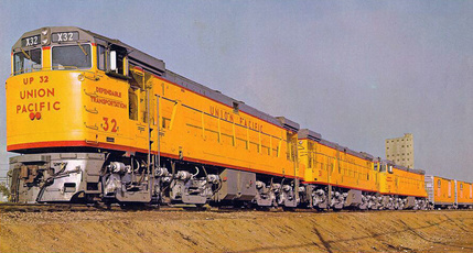
The GE U50 was an eight-axle, 5,000 hp (3,700 kW) diesel-electric locomotive built by GE Rail from 1963 to 1965. They were twin-engined locomotives, combining two 2,500 hp GE FDL-16 diesel engines on a common frame.
The U50 rode on four two-axle trucks, grouped in pairs linked by span bolsters, giving a wheel arrangement of B+B-B+B. The trucks and bolsters were re-used from scrapped UP turbine locomotives built by GE during the 1950s. The U50 was built in response to the Union Pacific Railroad's requirement, issued in the early 1960s, for a 15,000 hp (11,200 kW) 3-unit locomotive intended to replace the turbines. The design was effectively two U25B locomotives on a single frame; each diesel engine and generator powered only the two trucks at the same end. Three were delivered to the UP in October 1963, and three to the Southern Pacific Railroad in May and June 1964. Other locomotives built to this requirement were the EMD DD35A and the ALCO Century 855.
|
From Spookshow.net, the free N Scale Locomotive Encyclopedia (North American Prototypes) ...
Introduced: 1973 (Kato version), reintroduced in 1997 (as part of Con-Cor's "Rail Baron" collection.
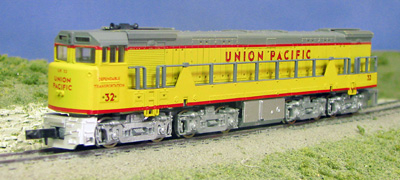
This locomotive was originally manufactured for Con-Cor by Kato (Japan), a relationship that lasted until 1989 when Con-Cor and Kato parted ways. As part of the split, all of the tooling for Con-Cor branded models was returned from Japan to the USA. Starting in 1997, Con-Cor starting producing "in-house" versions of this model for sale under their new "Rail Baron Collection" label (and with most of the actual manufacturing taking place in China). Kato used their same U50 mechanism for the Con-Cor/Kato Gas Turbine model (introduced in 1975).
These are nice looking models and decent enough performers. The mechanism is a variation on the horizontally split-frame design used in the Con-Cor/Kato Alco PA model of the 1960s. The motor is an open-sided 5-poler. Most (if not all) of the gearing is plastic. Only the outer two trucks provide pickup and propulsion. All 8 wheels on said trucks are geared and provide pickup (there are no traction tires). All current is transferred to the motor via the metal chassis itself, so there are no wires (apart from the ones for the headlight). Said headlight is directional and mounted on the cab end of the chassis (and unfortunately, it lights up the entire cab from within). These models have reasonably low-profile wheelsets and have no problems operating on Code-55 track. The Rapido-style couplers are truck-mounted (although the truck-mounting is actually prototypical in this instance).
Other decoder brands can be substituted for the install but you may need to make changes to this procedure as required.
|
Recommended Tools and Supplies
|
There are a few tools and supplies recommended for performing this decoder installation.
Tools:
Wire Strippers
Hobby Knife
Soldering Iron
Motor Tool
Multimeter
Supplies:
|
I am always asked what sound file should be used for the installation.
Here are my recommendations for the ESU LokSound 5 series decoders:
S0521 - Dual GE 16-FDL16 2EXH
|
This installation should be regarded as an expert-level project.
This is a hardwired installation that requires frame modifications, decoder modifications, shell modifications and is pretty much custom work all around. In addition, there are many opportunities for "sneak-shorts" and mechanical challenges that require a good bit of technical knowledge to work through.
So having said that... let there be rock!
|
Definitely one of the hardest parts of this installation are all of the frame modifications required to complete the installation as described here. I do have a small mill which makes easy work of the task and overall the amount of modification is pretty minimal all considering.
In case I have not published this elsewhere, milling model train frames can be tricky and it can get costly if you junk one. Having junked a hundred or so, I can speak with some authority on what works.
Model frames are typically make of a "sticky" kind of die-casting metal called Zamac. I have had nothing but success ever since I discovered the Roughing Carbide Square End Mill. This type of bit, wet or dry, makes quick work of the task. Speaking of it, I do like to cut wet with just a little bit WD-40 or similar fluid but that is mostly just to extend the life of the cutting tool.
To be sure it is said, milling frames does not require a great deal of precision. 99% of the time you are just making space for all of the new stuff.
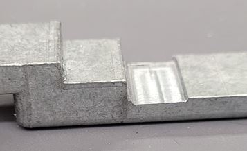
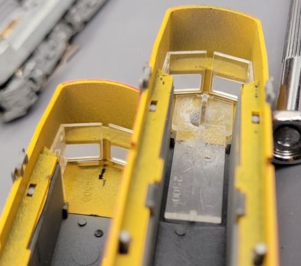
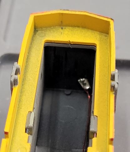
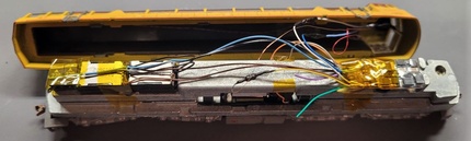
First, clear out some space out the box framing used to create a box for the original incandescent bulb and back-of-cab wall. I left the back-of-cab wall since it makes a nice view block in the cab.
|
I like to cut a small channel along the side of the frame to provide a clear path for the motor wires. I have pinched a couple between the frame and shell and it is a bad scene if you nick the insulation...
|
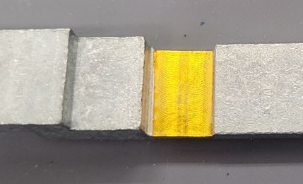
I chose to clear out a bit of material over the top motor brush cap. I think this is probably optional if the motor is insulated from the frame but I have the technology so why risk it.
Be sure to add a strip of Kapton Tape for extra protection. The easiest way to smoke a decoder is is to short out the motor circuit on the frame. Again, why risk it.
|
Build A Keep-Alive Assembly...
|
The keep-alive for this project is probably better labeled a capacitor block but keep-alive sounds so much better.
We are only adding 880uF of capacitance. It's not super cap grade but as i always say... anything more than 0 is worth the effort. If i were doing this again, i might be inclined to try the new ZIMO STACO1 Super Cap Stay-Alive Controller because I think there is room and it is now the smallest KA available.
|
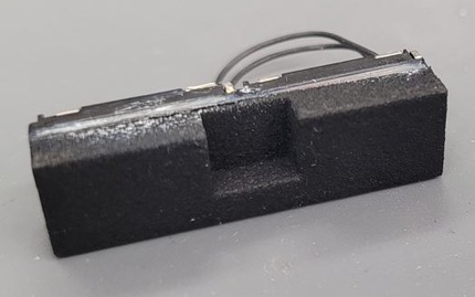
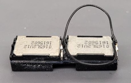
Build The Speaker Assembly...
|
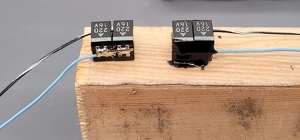
There was so much space available in this model on the rear shelf and this is such a big prototype, I decided that a dual cube was an absolute must.
One issue with this installation is the 9.8mm width of the frame/shell. Another issue with the project is the large protrusion in the middle of the space required for the frame assembly screw. You could use a pair of 8x12mm cubes and do nothing or... since cubes are kind of our thing... you could make a custom baffle to use a 9x16mm cube.
After gluing the speakers to the sound chamber, I added a pair of jumper wires in parallel giving the assembly a total impedance of 4 ohms.
*** WARNING: VERIFY THE IMPEDANCE OF THE DECODER TO BE USED AND WIRE IN PARALLEL OR SERIES AS REQUIRED ***
|
Build and Install the Lighting LEDs...
|
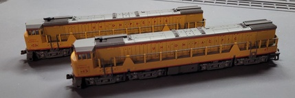
I actually converted a pair of these units for a 10,000 hP consist with lots of growl...
It turned out that one of my models was missing the front headlight / number board lens insert so I had a dilemma to work through.
I probably would have mounted a 1206 SMD to the back of light pipe if both models had one but one was missing.
|
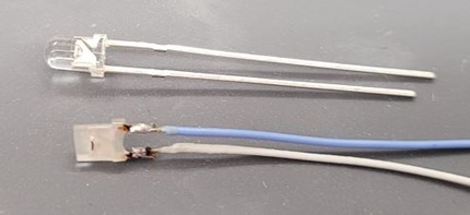
There are a lot of ways to solve this problem. I chose a custom solution because my hands shake too much to try to glue a LED in place between the cab windows and roof.
I do this a lot... I take a 3mm Round T1 LED and remove the extra lens material to make it a small rectangle-shaped LED. This way i can glue it to the roof far away from the windows but get it nice and tight behind the openings in the shell.
I also did this so I could add number board LEDs some day if I desire.
|
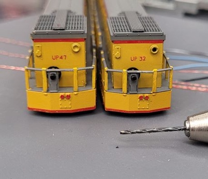
The rear headlight on this was just an unilluminated molded-on detail on the shell.
I simply drilled out the opening and mounted a 1206 SMD Pre-Wired LED to the inside of the shell over the new opening.
I don't show it here but I like to fill the openings with a nifty product i found at Lowes called Go2 Glue from LocTite. It has the consistency of epoxy but dries clear with very little shrink making it perfect for filling big holes like barrel headlight housings.
|
If you have done any homework on decoder installations, you have read about isolating the motor from the frame.
NOTE: THIS IS HOW TO ISOLATE THE MOTOR!
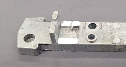
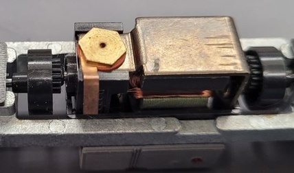
This is the most important step in this installation. The original design was typical of many older models. The leads off the motor brushes are metal tabs arranged to make contact with the frame.
For the top motor tab, I added clearance to the frame in an earlier step then simply wrapped the tab folded it so it lay on the side of the plastic motor frame. You could even trim it back if you wanted.
|
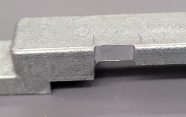
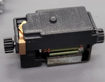
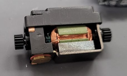
The bottom motor tab is wrapped around the outside of the plastic motor cradle.
|
I simply removed the cradle, tucked the tab inside and folded it lay nicely against the motor frame then snapped the cradle back on.
*** WARNING: Wrap the bottom of the frame and/or motor cradle with Kapton Tape for some extra protection ***
|
Installation and Final Assembly
|
With all of the prep work complete, we can get on with getting this one finished.
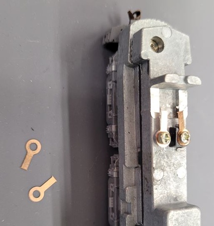
First things first, we have to get power to the decoder. One of my favorite methods for this is to drill and tap the frame for a 0-80 screw then use the SBS4DCC Ring Terminals and screws to create a solid connection between the decoder and frame.
This model is conveniently assembled with screws so no drilling or tapping required!
Just install a couple of ring terminals as shown as you reassemble to model.
|
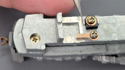
*** WARNING: Be careful of the sneak-short in this step ***
I chose to trim back the lead that sits on the plastic insulator to be sure i did not create a sneak-short caused by the ring terminal contacting the insulator anti-spin protrusion on the frame.
|
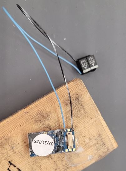
My next step was to connect the keep-alive to the decoder. Reference the decoder manual for the exact solder pads for your decoder.
I reassembled the decoder to the adapter board and wrapeed it up with Kapton Tape after the hot work was complete.
|
I try to work through every installation the same way.
Make left and right rail connections, always making right rail red, red is right.
Make the motor + and motor - connections. No magic here. It's work and it's trial and error. Make the connection - test run to verify forward is correct for the Normal Direction Of Travel (NDOT) for your model. Adjust connections and wire slack as required.
Make the speaker A and speaker B connections.
Retest for motion and sound.
*** NOTE: Refer to the manual for your decoder for the exact details / wire colors / connections ***
|
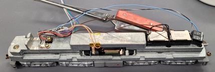
Once I have sound and motion, I finish up by connecting the lighting circuits.
After everything is carefully tested, I insulate the bare joints and wrap up the loose loose wires as required.
|
The installation is complete at this point and it's just a matter of doing "the big stuff" to refit the shell on the model. Go slow and be careful is all I can say.
|
The Test Run and Demonstration
|
So with that, the install is complete. Time to pour a glass and celebrate.
Or, if you are like me, curse, swear and try to sort out everything that wasn't quite as easy as it sounded here.
Once everything tests out and the job is done, you should be able to enjoy the sights and sounds just like the engine in this demonstration video.
N' Joy!
|
|
|