The Infamous 21MTC Interface Connector
|
Wow... The infamous 21MTC interface.
This interface was introduced by Märklin / ESU around 2005. The name stands for a 21-pin Marklin Trix Connector based on it's origins in the European model train market.
According to Richard Johnson of DCC Concepts in Australia,
This connector was never really planned for -It came about when ESU were creating a new Marklin decoder series (MFX) and Marklin needed also something with more pins to accommodate their 3 wire C-sine motor plus other functions. It was quite quickly adopted by several other ESU clients including Bachmann, and can be found in all continents now -especially in UK and Europe where many brands use it. The 21MTC has gone global now and it is also used AU locomotives on occasion. In USA it appears in Bachmann and PCM.
It looks like an ideal connector at first glance.
Plenty of pins for functions and sound. A few extra pins for cool stuff like the SUSI interface. Probably a few features and applications not yet imagined.
Well, maybe it's infamous, maybe it's not.
The 21MTC does seem to have a confused history, a recommendation for discontinuance, at least two undocumented designations, a non-standard application, and yet continues to grow in popularity in spite of it all.
The story is still being written today, July 4, 2015 and will no doubt face some new twist of fate or dramatic turn before the tome is published.
My conclusion is that there is no standard for this one regardless of what's on paper. I don't think anyone can say someone else didn't follow a standard with a straight face. The 21MTC connector is swerving down the road like a bachelor party at closing time...
This is a humble attempt to sort out some of the confusion and myths about it's use and provide some guidance for user to achieve their desired results.
|
The Recommended Practices
|
A good place to begin is with a quick look at the current version of the standards or RP's that provide the necessary direction for DCC decoder and model locomotive manufacturers to insure all of the parts of DCC work together and are reasonably interchangeable so that We The People ultimately benefit from the Freedom Of Choice we get when it all actually works together. Here are the MOROP Normen Europäischer Modellbahnen (NEM) and NMRA documents that govern the use of this interface connector.
|
Normen Europäischer Modellbahnen
Electrical Interface NEM660 21MTC
Nor
|
NMRA Recommended Practice 9.1.1
DCC Electrical Interface & Wire Color Code
|
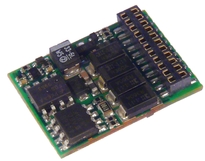
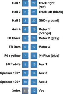
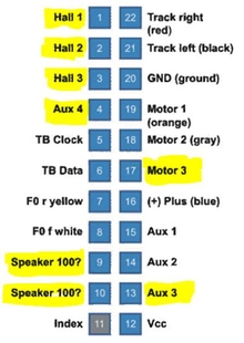
21MTC Electrical Interface Connector
|
Here is a picture of the connector and pin-out diagrams showing how it is to be used by decoder and locomotive manufacturers according to the NMRA spec and the NEM spec and an illustration of the differences.
|
21-pin interface to MTC standard based on 22-pin plug and socket connections (one anti rotation pin as index) directly on decoder.
|
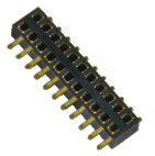
22-pin (2 x 11) socket connector based on a 1.27 mm pitch mounted on a decoder circuit board with Pin 11 removed or otherwise obstructed for use as an index point.
|
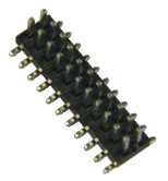
22-pin (2x11) mating plug mounted on a motherboard semi-permanently installed in the model to accept 21MTC Decoders with Pin 11 removed for use as an index point..
|
The NEM first adopted the NEM660 standard in 200?.
It appears the NEM standard has evolved over time to adapt the standard to advances in DCC technology and NMRA standard was not revised accordingly.
I really don't want to get into any finger-pointing about who did or didn't do what. It's not really my concern. I only need to know how this affects me, SBS4DCC, my customers, and any would-be customers reading this page.
Sometimes "IT" happens.
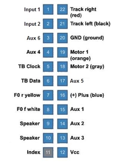
Specifically, the differences based on the current revision of the standards are as follows:
- Group 3 Pin 17 has been redefined from Motor 3 to AUX5
- Group 4 has been redefined from Hall Sensor 1,2,3 to Input 1,2 and AUX6
- AUX6 has been referenced in several ways depending on the date and translation of the NEM660 or NMRA standard reviewed including Zugbus-Daten, Ausgang 4, and Output 6 / Pick-up Control so it's actual use may be model or decoder specific.
- NEM Group 6: The speaker impedance is defined by the manufacturer and is as such documented.
- NMRA Group 6: The speaker will be wired between these Pins. The impedance shall be 100 Ohm.
- The NMRA standard omits Group 8 functions and combines them with Group 5 functions.
2 Starting Jan. 1st 2010, this connector will not be recommended for new locomotive designs. This will not invalidate the conformance of existing designs. Controllers for these connectors will continue to conform, as controllers for this connector will be required as long as locomotives with this connector exist.
The NMRA has subsequently marked this standard as follows:
Under review. Please contact NMRA S&C Dept. for update. 21MTC and PluX connectors are being modified and/or removed.
Consequently, TCS now refers to the 21MTC as a 21TCS connector.
According to TCS Tech Support,
The TCS 21 pin conforms to the current NMRA 21 pin standard. (Functions 3 & 4 are actual outputs just like the rest of the function outputs).
For clarity in this treatise and for identification of decoders for sale in the SBS4DCC store, I will simply refer to the two current variations as NEM 21MTC and NMRA 21MTC.
As of this writing, nearly every major model and DCC decoder manufacturer has a 21MTC decoder equipped model coming to market, including models from the DCC manufacturers themselves.
Who's confused?
It appears that the NMRA standard omits Group 8 functions and combines them with Group 5 functions.
Group 3 Pin 17 has been redefined from Motor 3 to AUX5
Group 4 has been redefined from Hall Sensor 1,2,3 to Input 1,2 and AUX6
Group 6: The speaker impedance is defined by the manufacturer and is as such documented.
Group 6: The speaker will be wired between these Pins. The impedance shall be 100 Ohm.
|
The good news is that there is some consensus about the differences and what really matters.
Here is another look at the pinout highlighting the pins that are affected.
|
Both ESU and TCS agree the primary concern is with the implementaion of AUX3 and AUX4.
ESU has implemented these as Logic Level Outputs.
Soundtraxx will be releasing a new model in August 2015 and has implemented these as Full Power "Amplified" Outputs.
TCS has implemented these as Full Power "Amplified" Outputs on the steam models and Logic Level Outputs on the diesel models.
Zimo has created the C version of decoder that has Logic Level Outputs and the D version that has Full Power "Amplified" Outputs to satisfy either standard and is probably not too concerned about the matter at this point.
The revision of Hall 1, 2, 3 and Motor 3 appears to mostly affect legacy Marklin models. This should not affect any recent, North American-based models.
Furthermore, the revision of speaker impedance is a legacy problem for ESU at this point. The LokSound v3.5 was the only decoder to my knowledge to ever specify 100 ohm speaker impedance. This model was replaced in 2011 by the v4.0 which specifies speaker impedance of 4-16 ohms, the same as nearly every other decoder on the market.
|
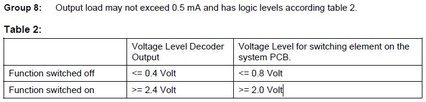
A Logic Level Output uses a tightly controlled low voltage signal that can be used as an input or an output.
According to the NEM spec:
|
Zimo defines the logic level output as follows...
"Logic Level" outputs, also called "unamplified" outputs or "logic level" referred to, which at the terminal a voltage level set (0V for "off", 5V for "on"), the max available has an internal protection resistor 10 K (i.e. 0.5mA output current), which by external gain can be made available, which can be installed by yourself, but there is also the M4000Z for this, see the detailed instructions for the decoder.
|
It appears the first use of the Logic Level Output was to provide additional control capability for Marklin C-Sine Soft Start drives.
From what I can gather, tangible features that use the Logic Level Output are really just beginning to be developed by model manufactures.
It sounds like there are some really cool features on the way that might not be possible otherwise, or at least not with a NMRA 21MTC decoder installed.
We will wait anxiously to see how the new features advance the hobby.
|
ZIMO decoders have different types of outputs, the presence, number and capacity of the various outputs varies across the decoder families : - "Normal" (often called "amplified") function outputs, as exists in decoders for all manufacturers, and are (technically) "open-collector" or "open drain" outputs to which head lamps, other lights, smoke generators, coupling coils and other devices may be connected, with the second terminal of each device - connected to the "common positive pole" of the decoder (blue wire), or - connected to the "low voltage" (purple wire), if the decoder has such a wire (MX632V, MX632W); - It is also possible to connect the second terminal of a device with the left or the right rail, (In some vehicles this is through the conductive chassis, often where lights are used this is the case), with the device (in this case) has current flowing through it only half the time (for symmetrical DCC signal), So for example light with reduced brightness light (but in the perception but more than HELB so bright ..). - "Logic Level" (often called the "unamplified") outputs, see below!. - "LED Outputs", see below! - Outputs for Servo Control, see below! "Logic Level" outputs, also called "unamplified" outputs or "logic level" referred to, which at the terminal a voltage level set (0V for "off", 5V for "on"), the max available has an internal protection resistor 10 K (i.e. 0.5 mA output current), which by external gain can be made available, which can be installed by yourslef, but there is also the M4000Z for this, see the detailed instructions for the decoder. ATTENTION: "logic level" outputs are active in the default configuration of the decoder NOT because they use the same ports as the SUSI interface (clock and data) as well as the servo-control lines. The decision on the use of these common terminals is done with CV # 124: Bit 7 = 0 -> SUSI Bit 7 = 1 -> "Logikpegel" and the CV's # 181, 182 (if these are set: the common terminals are used for servo controlt). "Logic level outputs" of the "C" and "D" types: In all decoders with 21-pin "MTC" interface (either a "D" - type or a "C" - type, e.g. MX631D. MX631C or MX644D), these two variants (C and D) differ in each case by the execution of the function outputs FA3 and FA4: "D" - type: FA3, FA4 are "normal" amplified output, "C" - Outputs: FA3, FA4 are "logic level" outputs
|
The Bottom Line, The Net Effect
|
The discrepancy between the standards really ONLY affects AUX3 and AUX4. Technically it affects all Group 8 Functions but TCS and Soundtraxx do not offer decoders that use AUX5 and AUX6 at this time.
This means the differences in the standards generally only apply to 6 (or more) function decoders.
The net effect you will see if using an incompatible combination is that AUX3 and AUX4 will not work properly.
All other features of any decoder remain the same and are fully compatible with any model.
If you don't need any of this for your application, none of this matters.
If you do, validate your application and shop wisely.
|
It turns out that, according to numerous experts and manufactures, it appears using a NEM660 21MTC decoder on a NMRA 21MTC motherboard or vice-versa WILL NOT cause any damage to either product.
The tangible results to "We The People" vary depending on the combination of decoder and motherboard used.
Decoder Motherboard AUX3/4 V@MB
NEM660 21MTC NEM660 21MTC 2.0V 0.5mA Max
NMRA 21MTC NMRA 21MTC Track Voltage
NEM660 21MTC NMRA 21MTC 2.0V 0.5mA Max
NMRA 21MTC NEM660 21MTC Fault
The most common application of AUX3 and AUX4 today are for use as traditional lighting outputs.
Basically, we connect LEDs to them and turn them ON and OFF. This is sure to change in the future.
If you are not sure if the output is logic level or full power, the easiest test is to connect a LED, with current limiting resistor of course, to the output and turn it on. If it lights it is a Full Power "Amplified" Output. If it doesn't, it is probably a Logic Level Output.
You can amplify the AUX3 and AUX4 outputs of a NEM-based decoder for use with lighting by using an adapter board.
You cannot un-amplify the outputs of a NMRA 21MTC-based decoder for use as a Logic Level Output.
You should use caution with regards to AUX3 and AUX4 if you choose mix NEM and NMRA versions.
|
Decoders and Adapter Boards
Decoders and Adapter Boards
|
ZIMO offers the male and female connectors available separately for use in building harnesses and other adapters.
They also offer the PluX22 male connector that can be substituted since the only difference is the location of the index pin and these have not been "indexed", so to speak.
|
ZIMO NEM658 PluX22 - NEM660 21MTC 22-pin Female Connector
This is a 22-pin (2x11) female header on 1,27 mm pin spacing to make a wired ZIMO C or D - Type 21MTC decoder from a normal hardwired decoder, e.g. convert a MX630 to a wired MX630D.
This is also the mating connector for a ZIMO P8/12/16/22 - Type decoder, e.g. MX600P12, MX645P22, and can be installed in a model without an interface to make the decoder easy to replace.
This connector conforms to NMRA RP 9.1.1 Standard for Electrical Interface Connectors and the NEM658 and NEM660 Standards.
|
ZIMO NEM660 21MTC 22-pin Male Connector
This is the mating connector for a ZIMO C or D - Type 21MTC decoder, e.g. MX634C, MX644D, and can be installed in a model without an interface to make the decoder easy to replace.
This is also a 22-pin (2x11) male header on 1,27 mm pin spacing to make a wired ZIMO P22 - Type decoder from a normal hardwired decoder, e.g. convert a MX630 to a wired MX630P22.
This connector conforms to NMRA RP 9.1.1 Standard for Electrical Interface Connectors and the NEM658 and NEM660 Standards.
|
ZIMO NEM658 PluX22 22-pin Male Connector
This is a 22-pin (2x11) male header on 1,27 mm pin spacing to make a wired ZIMO P22 - Type decoder from a normal hardwired decoder, e.g. convert a MX630 to a wired MX630P22.
This connector conforms to NMRA RP 9.1.1 Standard for Electrical Interface Connectors and the NEM658 Standard.
|
Decoders and Adapter Boards
|
This is not intended to be an all-inclusive list of products that use the 21MTC connector but it will provide an idea of the products carried by SBS4DCC and how they have implemented AUX3 and AUX4.
|
| Brand |
|
Function Outputs |
|
|
| Series |
Model |
Full Power Fn |
Logic Level Fn |
Aux3-6 Logic Amp |
Standard |
Comments |
|
|
|
|
|
|
|
| Bachmann E-Z DCC |
|
|
|
|
|
|
| E-Z Command |
36557 |
4 |
0 |
|
NMRA |
|
| Soundtraxx Sound Module |
44951 |
|
|
|
NA |
HO B&O EM-1 2-8-8-4 |
|
44952 |
|
|
|
NA |
On30 2-4-4-2 |
|
44953 |
|
|
|
NA |
On30 Stearns Heisler |
|
44955 |
|
|
|
NA |
On30 Whitcomb 50T Center Cab |
|
44956 |
|
|
|
NA |
HO Scale 50T 2-Truck Climax |
|
|
|
|
|
|
|
| CT Electronik |
|
|
|
|
|
|
| SL |
SL51-MTC |
8 |
0 |
|
NMRA |
|
|
|
|
|
|
|
|
| Digitrax |
|
|
|
|
|
|
| Series 6 |
DH166MT |
4+(2) |
(2) |
|
NEM/NMRA |
Convertible |
|
SDH166MT |
4+(2) |
(2) |
|
See |
To Full Power |
|
SDXH166MT |
4+(2) |
(2) |
|
Notes |
Or Logic Level |
|
|
|
|
|
|
|
| ESU |
|
|
|
|
|
|
| fX v3.0 |
52621 |
4 |
2 |
|
NEM |
|
| fX v4.0 |
54621 |
4 |
2 |
|
NEM |
|
| Basic |
52692 |
2 |
1 |
|
NEM |
|
| Standard |
53614 |
4 |
2 |
|
NEM |
|
| LokPilot |
54614 |
4 |
2 |
|
NEM |
v4.0 Multi Protocol |
|
54615 |
4 |
2 |
|
NEM |
v4.0 DCC |
|
64614 |
4 |
2 |
|
NEM |
v4.0 Marklin M4 |
|
64618 |
4 |
2 |
|
NEM |
v4.0 Marklin M4 |
|
64633/34/35 |
4 |
2 |
|
NEM |
v4.0 M4 Digital Set |
| LokSound |
52499 |
4 |
2 |
|
NEM |
v3.5 |
|
54499 |
4 |
2 |
|
NEM |
v4.0 |
|
64499 |
4 |
2 |
|
NEM |
v4.0 M4 |
|
73900 Rev 1 |
4 |
2 |
|
NEM |
Select |
|
73900 Rev 2 |
4 |
4 |
|
NEM |
Select and OEM |
| Adapter Boards |
51954 |
|
|
2 |
NEM |
|
|
51966 |
|
|
|
NEM |
For Marklin Only |
|
51967 |
|
|
|
NA |
MTC Decoder to Hardwire |
|
51968 Rev 1 |
|
|
2 |
NEM |
|
|
51968 Rev 2 |
|
|
4 |
NEM |
|
|
51970 |
|
|
4 |
NEM |
Plus (2) Servo |
| Test Stand |
51900 Rev 2 |
|
|
2 |
NEM |
MTC Connector and Terminal Block |
|
51900 Rev 3 |
|
|
4 |
NEM |
MTC Connector and Terminal Block |
|
|
|
|
|
|
|
| Lenz |
|
|
|
|
|
|
| Silver |
Silver21+ |
5 |
|
|
NMRA |
|
|
|
|
|
|
|
|
| NCE |
|
|
|
|
|
|
|
D16MTC |
4+(4) |
(4) |
|
NEM/NMRA |
Convertible |
|
|
|
|
|
|
|
| SoundTraxx |
|
|
|
|
|
|
| Econami ECO-21P |
881003 Steam |
6 |
|
|
NMRA |
|
|
882003 Diesel |
6 |
|
|
NMRA |
|
|
883003 Electric |
6 |
|
|
NMRA |
|
|
881006 Steam |
4 |
2 |
|
NEM |
|
|
882006 Diesel |
4 |
2 |
|
NEM |
|
| Tsunami2 |
884003 TSU-21P |
4 |
2 |
|
NEM |
TSU-2 Steam |
|
885009 TSU-21P |
4 |
2 |
|
NEM |
TSU-2 EMD |
|
885010 TSU-21P |
4 |
2 |
|
NEM |
TSU-2 GE |
|
885011 TSU-21P |
4 |
2 |
|
NEM |
TSU-2 Alco |
|
885012 TSU-21P |
4 |
2 |
|
NEM |
TSU-2 Baldwin |
|
886003 TSU-21P |
4 |
2 |
|
NEM |
TSU-2 Electric |
|
|
|
|
|
|
|
| TCS |
|
|
|
|
|
|
| EU |
EU621 |
6 |
|
|
NMRA |
|
|
EU621X |
6 |
|
|
NMRA |
|
|
EU821 |
4 |
4 |
|
NEM/NMRA |
Convertible |
| WOW-Sound |
WOW-121 Steam |
6 |
|
|
NMRA |
Oversized Board |
| WOW-Sound |
WOW-121 Diesel |
4 |
4 |
|
NEM |
Oversized Board |
| Adapter Boards |
1358 - MTC-HW |
|
|
|
NA |
MTC Motherboard to Hardwire |
|
1543 P2K MB1 |
|
|
0 |
NMRA |
|
|
1544 Bach MB1 |
|
|
0 |
NMRA |
|
|
1545 Bach MB2 |
|
|
0 |
NMRA |
|
|
1546 Bach MB3 |
|
|
0 |
NMRA |
|
|
1557 Bach MB4 |
|
|
0 |
NMRA |
|
|
1615 RTR-MB1 |
|
|
4 |
NEM |
* Short MTC Plug |
|
1616 GEN-MB1 |
|
|
4 |
NEM |
* Short MTC Plug |
|
1617 IB-MB1 |
|
|
4 |
NEM |
* Short MTC Plug |
|
1618 IB-MB2 |
|
|
4 |
NEM |
* Short MTC Plug |
|
1619 IB-MB1-NC |
|
|
4 |
NEM |
* Short MTC Plug |
|
1620 IB-MB2-NC |
|
|
4 |
NEM |
* Short MTC Plug |
|
1622 AK-MB1 |
|
|
4 |
NEM |
* Short MTC Plug |
| Test Stand |
1595 Decoder Tester |
|
|
4* |
NEM & NMRA |
*21TCS (NMRA) and 21MTC Connectors |
|
|
|
|
|
|
|
| ZIMO |
|
|
|
|
|
|
| Function |
MX686D |
8 |
|
|
NMRA |
|
|
MX687WD |
8 |
|
|
NEM |
|
| Small Decoder |
MX631C |
4 |
2 |
|
NEM |
|
|
MX631D |
6 |
|
|
NMRA |
|
|
MX632C |
6 |
2 |
|
NEM |
|
|
MX632D |
8 |
|
|
NMRA |
|
|
MX632VD |
8 |
|
|
NMRA |
1.5V Normal Outputs |
|
MX632WD |
8 |
|
|
NMRA |
5.0V Normal Outputs |
|
MX634C |
4 |
2 |
|
NEM |
Convertible to D via CV8 |
|
MX634D |
6 |
|
|
NMRA |
Convertible to C via CV8 |
| Small Decoder Sound |
MX640C |
6 |
2 |
|
NEM |
|
|
MX640D |
8 |
|
|
NMRA |
|
|
MX642C |
6 |
2 |
|
NEM |
|
|
MX642D |
8 |
|
|
NMRA |
|
|
MX644C |
4 |
4 |
|
NEM |
|
|
MX644D |
8 |
|
|
NMRA |
|
| Adapter Boards |
ADAMTC |
|
|
4 |
NEM |
For C Model Only |
|
ADAMKL |
|
|
4 |
NEM |
For C Model Only |
|
Fit and Interchangability
|
For the record, I wish to date stamp this topic as current as of May 22, 2016. Like everything else on this page, the products and information are subject to update and revision...
I should note before going any further that I did not find one instance where there were fit-up issues with any product of the same brand. ESU works fine with ESU, TCS works fine with TCS, ZIMO works fine with ZIMO.
The most common question I am asked about the 21MTC connector is will this decoder work with that adapter board or with OEM board in such and such engine.
In theory, the answer should always be yes and without qualification or exception. There is a standard for this after all...
In practice, well, there are a few issues worth noting.
First, all characteristics of product size is defined by the dimensions on the previously referenced standards. Since the NMRA standard is under review and allows for a variety of sizes that I have yet to see used by any manufacturer, I am going to reference the standards called out in the NEM standard.
Second, I am only looking at aftermarket products from the DCC OEM's. I just don't have the resources to dive into the vast array of locomotive mother boards. Just keep in mind, all of the basic principals I am discussing still apply.
|
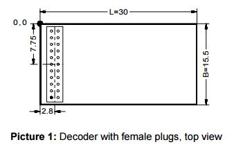
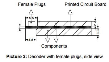
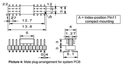
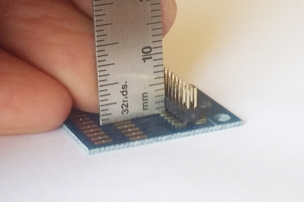
Section 2.1 of the standard specifies the mechanical characteristics of the format. Length and width (Picture 1) are important but maximum component height on each side of the decoder (Picture 2) and dimensions of the mating adapter (Picture 4) are probably the most critical.
|
I have identified a few issues that make interchangeability a bit of an issue.
First, in all cases, the height of the mating surface of the male connector on the adapter board is too low.
The standard calls for 3mm (reference Picture 4).
The ESU 51967 board was closest at 2.81mm.
The TCS and Zimo boards measure 1.50mm.
The exposed pin length ranged from 2.92 to 3.30mm so that is probably close enough to not cause issues.
The exposed pin length ranged from 2.92 to 3.30mm so that is probably close enough to not cause issues.
The exposed pin length ranged from 2.92 to 3.30mm so that is probably close enough to not cause issues.
|
 |
| ESU 51967 21-HW - 21MTC Adapter Board |
|
|
 |
| TCS 1622 AK-MB1 Motherboard Adapter Board |
|
|
 |
| Zimo ADAMKL MTC-21 Adapter Board with Screw Terminals |
|
|
 |
| Zimo ADAMTC MTC-21 Adapter Board with Solder Pads |
|
|
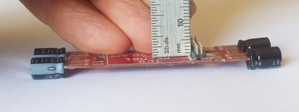
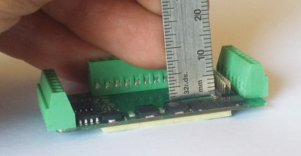
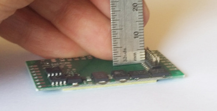
The issue here is that the standard allows for 3.3mm from the bottom of the decoder board to the top of the adapter board. By default this means there is 0.3mm of interference built into the standard when all parts are at the maximum limit.
The ESU Select decoder measures 2.85mm from bottom of board to top of tallest component.
The TCS board measures 1.55mm from bottom of board to top of tallest component.
The Zimo board was the thinnest at 0.91mm from bottom of board to top of tallest component.
The most extreme example is the Soundtraxx board which measures 3.3mm from bottom of board to top of tallest component.
The net effect is that you must force the decoder into an unnatural position to get any pin engagement.
|
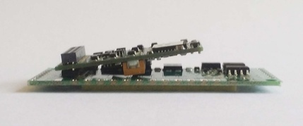 |
| Econami Decoder Mated To The Zimo ADAMTC Adapter Board |
|
|
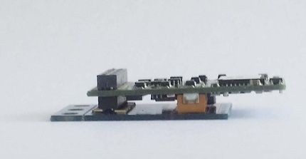
Even the ESU decoder mated to the Zimo or TCS adapter boards produced a marginal fit.
|
 |
| ESU Select Decoder Mated To The TCS AK-MB1 Adapter Board |
|
|
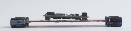
Unfortunately, the TCS and Zimo connectors are just too short to get any pin engagement with the Soundtraxx decoder. The fit is really just impossible.
When the Soundtraxx Econami decoder is mated to the ESU 51967, you can get full pin engagement but the board must be forced onto the pins such that it sits at a very slight angle.
Unfortunately, the TCS and Zimo connectors are just too short to get any pin engagement with the Soundtraxx decoder.
|
 |
| Econami Decoder Mated To The ESU 51967 Adapter Board |
|
|
Second, there appears to be two different brands of connectors being used by the various OEMs.
The plastic spacer on male connector used on the ESU adapter board is clearly thicker and the pins are clearly longer as compared to the TCS and Zimo adapter boards.
This is the most likely cause of the first fit up problem.
The other obvious difference is that the sockets of one brand of female connector have inserts where as the other type does not.
While I have no proof beyond gut feel and hands on evaluation, it seems
|
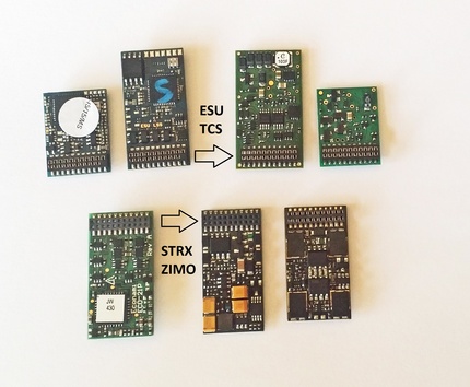 |
| Two Different Types Of 21MTC Connector Used By OEMs |
|
|
I do not have any hard data from pull tests and such but my gut feel is that you get much tighter pin engagement and improved pin contact with the type of connector having inserts.
The third issue I have found is limited to TCS so far.
As noted elsewhere on this page, the TCS WOW decoders are wider than the spec allows because of their use of the micro SD card for memory.
|
 |
| TCS WOW with Zimo ADAMTC |
|
|
The oversized decoder board can interfere with components on the adapter board depending on how they adapter board is laid out.
|
Digitrax Application Notes
|
CV64 - Logic Level or 12v 21-pin Function Outputs
Digitrax Series 6 MT decoders can be configured via CV64 for compatibility with either Logic Level or 12 Volt function formats for outputs F3 and F4.
By default CV64 is set to a value of 0 for Logic Level compatibility. This is the most common configuration
for locomotives using the 21MTC interface.
Setting CV64 to a value of 64 will set a bit for function compatibility to 12v format comparable to that of F0, F1, and F2 .
|
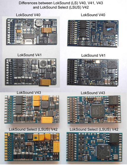
ESU 54499 and 73900 Keep Alive and Aux6
In order to use a keep-alive module with the ESU mid-size V4.0 and Select decoders, you must disable Aux6 and SUSI for the module to perform properly.
In doing so, you will lose the functionality of Aux6 for lighting purposes.
|
ESU 51900 Rev 2 LokTester AUX3 and AUX4 Outputs
Note that all AUX3 and AUX4 connections on the LokTester are amplified on the test stand per the NEM standard.
This includes the AUX3 and AUX4 connections on the hardwire screw terminal connector.
Refer to my ESU 51900 LokTester Modifications page for a simple work-around to this situation to make it compatible with the NMRA standard.
|
ESU OEM-Spec 8-Function 21MTC LokSound Select
Note that there is an OEM-spec 8-function LokSound 21MTC Selects first used in the new Horby-Rivarossi U25C. These have made their way into other locos including the Bowser SD40-2.
According to ESU, all 73900 Selects are now 8-function; 4 standard output plus 4 logic level outputs.
As of this writing the, June, 17, 2016, the V4.0 54499 is still 4 standard output plus 2 logic level outputs.
This version of the decoder utilizes AUX5 and AUX6 for lighting in the model. These are Group 8 functions according to the NEM standard and, as such, are Logic Level Outputs.
|
 |
| Variations of ESU 54499 and 73900 Hardware |
|
|
The 8 function models can be identified by changes to the hardware as shown; the LokSound Select (LSUS) V42 is the only 8 function model.
The 8 function models can also be identified by the boot code (0.2.0026 and build date (1/17/2014).
The 8 function models can be identified by the build date
The 8 function models can be identified by the build date
|
Scale Trains HO Scale SD40-2
SD40-2 Non Silenced Exhaust Version
97436 LSV4.0 LokSound File. *Must use LSV4.0, File will not work with a LokSound Select*
97636 LPV4.0 Non Sound LokPilot File. *Must Use a LPV4.0, File with not work with a LP Standard*
SD40-2 Silenced Exhaust Version
97456 LSV4.0 LokSound File. *Must use LSV4.0, File will not work with a LokSound Select*
97656 LPV4.0 Non Sound LokPilot File. *Must Use a LPV4.0, File with not work with a LP Standard*
The Sound file contains a "Class Light" feature which allows for Cycling Aux2, Aux7, and Aux8 when using a 21MTC V4.0 decoder.
If you wish to change the Mapping you must assign the "Class Light" "Sound" to the function button of your choice and and be sure each Aux listed above is set to "Dimmable Headlight".
Please note the LPV4.0 does not have this class light feature.
It is already set to allow the different color class lights to work on separate functions. Per Matt Herman of ESU, LLC, regarding remapping or modification of the operation of class lights...
The ScaleTrains SD40-2s are already using 12(!) outputs by using a special motherboard providing some extra logic. They also include the ESU PowerPack on this motherboard. (This is the reason they are using a V4.0 btw…) To separate the front and rear class lights would require 3 additional outputs as you would need one more output for each color. Unfortunately the extra outputs are simply not available to do so as they are all currently used for other functions.
Gone are the days of only being to have Front light and Rear light pre-installed…. But 15 outputs plus a PowerPack is still a little bit out on the horizon. ;)
The possibility would exist to add an ESU LokPilot FX decoder which would give you the additional outputs needed but it would have to be hardwired. For what it’s worth the rear class lights on an SD40-2 were rarely used so I have seen some modelers simply disconnecting them but this is only a suggestion… The
ScaleTrains SD40-2s are already using 12(!) outputs by using a special
motherboard providing some extra logic. They also include the ESU PowerPack on
this motherboard. (This is the reason they are using a V4.0 btw…)
To separate the front and rear class lights would require 3 additional outputs
as you would need one more output for each color. Unfortunately the extra
outputs are simply not available to do so as they are all currently used for
other functions.
Gone are the days of only being to have Front light and Rear light
pre-installed…. But 15 outputs plus a PowerPack is still a little bit out on
the horizon. ;)
The possibility would exist to add an ESU LokPilot FX decoder which would give
you the additional outputs needed but it would have to be hardwired. For what
it’s worth the rear class lights on an SD40-2 were rarely used so I have seen
some modelers simply disconnecting them but this is only a suggestion…
|
ESU 73900 Select 21MTC Speaker Wires
CLICK HERE for a page on my site I wrote a while ago that provides a description and warning about the speaker wires on the 73900 Select 21MTC decoder.
|
Compatibility of F3, F4, F5, F6 with ‘logic level’ (EU) locomtives:
The D16MTC can be configured via CV115 for compatibility with either logic level or full power for outputs F3, F4, F5 and F6.
By default CV115 is set to a value of 0 for full power output compatibility comparable to the format of function outputs F0, F1 and F2.
If you have a locomotive that requires logic level set CV115 to a value of 1 will provide for compatibility with logic level locomotives.
One indication of the wrong setting for CV115 is that function will be off when they should be on and vice versa.
Always test your decoder installation on a current limited programming track before trying it on full track power.
We recommend that the first full power testing be done on regular DC.
The decoders should be driven by a good quality smooth DC power unit.
Power packs with pulse power systems such as "tracking control", etc. may give unpredictable operation.
CV115 Output 5-8 configuration. 1=outputs 5-8 are logic level (EU), 0=full power (US)
|
SoundTraxx Application Notes
|
TCS Decoder Tester
The TCS Decoder Tester is the first reference to the 21TCS connector.
According to TCS, the pinout for this connector is identical to the NMRA standard. AUX3 and AUX4 are not amplified from this connector.
The 21MTC connector follows the NEM standard and has transistors on-board to amplify the Logic Level Outputs.
|
WOW-121 Size vs. Standard
The NMRA and NEM standards also show conflicting requirements for the physical size of the decoder.
The NEM standard seems pretty clear, 30.0 x 15.5 x 6.5 mm.
The NMRA standard allows three different sizes and states the Size Group should be noted on the package. None of the size groups match the NEM standard.
The TCS WOW-121 Steam decoder measures 32.6 x 17.5 x 5.5 mm which does not match any standard, NEM or NMRA.
The width seems to be driven by the Micro SD memory card. I did note this created a problem trying to connect the decoder to the ESU 51900 LokTester since the 21MTC plug is positioned next to Screw Terminal Block as spaced according to the NEM footprint.
This may or may not be an issue in model locomotives.
|
Bachmann Application Notes
|
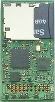
Well, it's no surprise Bachmann is a mess. It's Bachmann.
Where to begin...
Bachmann Branchline, which are predominantly models based on UK prototypes, offers a decoder model 36557 which is a 21-pin E-Z Command 4-function 1A decoder with back EMF.
|
Since it is a 4-function decoder, it really won't matter which spec it follows but apparently they have dubbed their model 21DCC.
Huh? 21DCC? I guess that follows the NMRA standard?
|
I found this wiring diagram for an un-referenced sound model decoder on the Bachmann US website DCC support page that refers to speaker impedance of 100-ohm so it could be either standard depending on the date it was developed.
Again, since it is only four function it probably doesn't matter except for the speaker impedance.
Since it is 100-ohm, it would have to be for an ESU LokSound v3.5 decoder which means it would most likely follow the NEM standard.
|
Then there's the newer Sound Modules made by Soundtraxx that use the 21MTC connector to interface with a motherboard in the loco.
I can't get any documentation beyond a manual and CV list for these so I can only speculate.
Based on the information I did get, the motherboard is a traditional motor-function decoder that pass back-EMF voltage to the Sound Module to influence the sound playback.
I could not obtain a pinout for this so can only guess that it does not follow any standard and is simply a proprietary use of the 21MTC connector.
I would not use this in any application except as advertised unless it was simply an experiment to find the hidden smoke.
From the Soundtraxx website...
ginning in late 2011 Bachmann Spectrum locomotives that are ordered with DCC come equipped with a SoundTraxx Mobile Decoder that has a 21-pin plug and a speaker already installed. Bachmann also sells a separate sound module to plug into the 21-pin connector. The sound module and the mobile decoder plugged in together act the same as the Tsunami found in the 2009-2010 released Spectrum models. For a complete breakdown of all of the CVs and Tsunami’s capabilities, please reference the Bachmann Quick Start Guide, User’s Guide and Technical Reference on our website or visit www.bachmanntrains.com.
Each Bachmann sound-equipped locomotive comes with multiple whistles to allow you to customize the locomotive to your personal tastes or more closely match your prototype railroad. Bachmann sound-equipped locomotives include most of the amazing features found in all aftermarket Tsunami decoders, including 16-bit digital sound and advanced motor controls. Listed below are the locomotive models that currently are or will be shipped with Tsunami Digital Sound Decoders installed. Select your model from the list to link to a quick reference document specific to that engine.
Beginning in late 2011 Bachmann Spectrum locomotives that are ordered with DCC come equipped with a SoundTraxx Mobile Decoder that has a 21-pin plug and a speaker already installed. Bachmann also sells a separate sound module to plug into the 21-pin connector. The sound module and the mobile decoder plugged in together act the same as the Tsunami found in the 2009-2010 released Spectrum models.
Hahaha! I guess we can call this one a 21STX...
|
Mike Garber provided some additional info on the Bachmann modules.
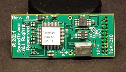
The format is marked TSX-21D.
Mike also confirmed the function of this board. "It is only a sound module as I removed it from the decoder/light board and the loco runs great and CV’s can be adjusted, so the module is sound only."
|
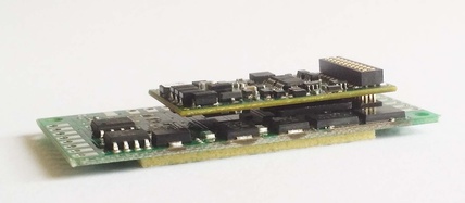
 |
| Photo Courtesy of Mike Garber |
|
|
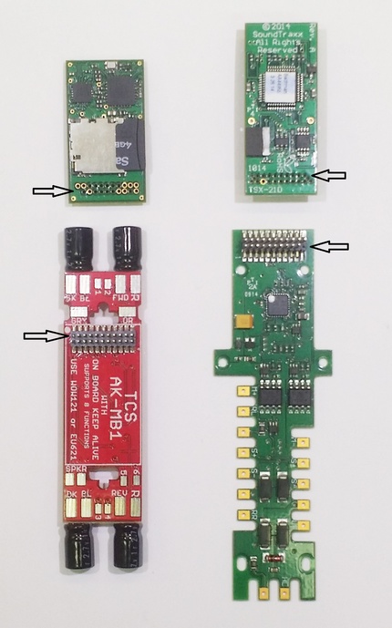 |
| Comparison of Index Pin Location of TSX21D and 21MTC Components |
|
|
I note that the TSX21D does not follow the MTC standard for pin out.
Specifically, the TSX21D uses Pin 22 for the Index pin.
The MTC standard uses Pin 11.
You can orient the various items to get them together but the result is not natural which should give reason to question if they are supposed to be used together.
|
Amplify Logic Level Outputs
|
Phil Dunlop, an expert on LokSound Sound File development, has provided this diagram which clarifies the pinout and connections on the ESU 51967 Adapter Board and adds transistors to amplify the Logic Level Outputs.
|
I have offered the SBS4DCC AUX 3-4 Function Board for several years that is a clean and inexpensive solution for amplifying Logic Level Outputs.
The circuit and components are more-or-less identical to the information found in the ESU 51967 Board Modification Diagram.ESU 51967 Adapter Modification Diagram
|
It in German I think so I'll let you stumble through the translation.
|
Please forward comments, additional content and questions about this matter to sales@sbs4dcc.com.
|
|
|