The Chicago & South Western System II
|
Scheduled Inauguration Date December, 2023
Benchwork Fabrication Started December, 2021 Construction Permit Issued November, 2019
|
Ten years, five jobs, three homes and one big move from Indiana to Alabama later, I can say with great joy, construction of the second generation of the C&SW has commenced.
This is actually my seventh layout in both HO and N scales since I caught the fever way back in 1978 or so... eight if you count the Tyco Orbiter on the kitchen floor at Grandview...
I started designing this edition about ten minutes after I started tearing down the last layout. I have worked through a thousand design concepts and iterations and tested hundreds of techniques.
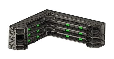
The final version is a stand-alone, modular tri-level designed to utilize vertical space with minimum footprint for maximum mainline runs but still leave room for SBS4DCC operations in any two car garage.
|
The final design of the N-Scale (1:160) layout had to fit some key criteria to be sure I got what I wanted this time.
Layout & Benchwork
- Must fit in a two car garage
- Must have room for SBS4DCC operations
- Must be multi-level to utilize vertical space
- Must be relocatable and expandable modular design
- Must be rigid, free-standing construction
- Must have 1 inch foam table tops for noise and below-grade scenery elements
- Maximum depth is 24 inch for easy reach and access
- Must be enclosed when not in use
- Must have unobstructed access to trains and track
- Decks heights must be reachable by 5'7" me by sitting or standing... no ladder or grippers
- Must feature textbook DCC-only control and wiring (duh...)
- Must have access to wiring terminations from layout facia
- Must be suitable for car card & waybill operations
- Must utilize modern, dimmable RGB-CCT type LED lighting strips as required
Track Work
- Must be capable of continuous running or point-to-point operations
- Must have staging at each end of point-to-point mainline
- Will develop free-lanced track plan after basic elements are established
- Will use only Kato UNITRACK for simplicity and reliability
- Will utilize helix to transition between levels using maximum radii for minimum grade (Kato 20-185 & 20-186 Tack Sections)
- Minimum clearance between helix decks is 2.13 inches based on top-of-deck to top-of-car clearance for modern-era double stack cars
Rolling Stock
- Will use only Micro-Trains, Atlas Accumate, and Kato Knuckle couplers
- Will use only metal wheels for maximum track cleanliness
- Will follow NMRA recommended practice for car weight
|
It took a good bit of design work and experimentation to meet the criteria of all these givens and druthers.
I am an engineer and designer by trade so I leveraged those skills and the power of CAD to design what I would describe as non-traditional benchwork.
I tested at least a dozen construction concepts and failed. I almost settled on a scaled down concept using out-of-the-box modules because I couldn't find a resource or technique to fabricate my grander vision.
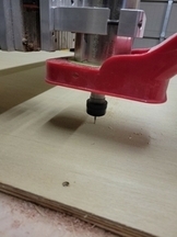
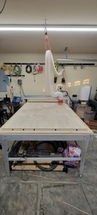
As luck (or fate) would have it, I discovered a manufacturer within minutes of committing to the easy road. The manufacturer, M+B LLC, could fabricate the components using a CNC router and they are literally two miles down the road.
You can contact M+B LLC at 256-230-7029 or by email at (mackenzieplusbrian at gmail dot com) to discuss your custom projects.
We fabricated and assembled a test module in December of 2021 to work out the details of function, fit and finish.
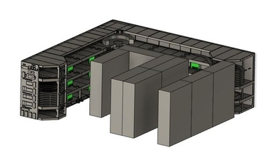
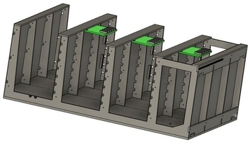
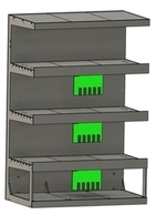
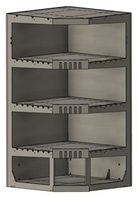
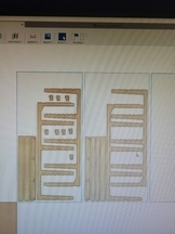
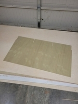
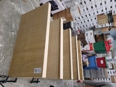
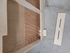
The basic element of the design is the vertical E-member fabricated from 1/2 inch plywood.
|
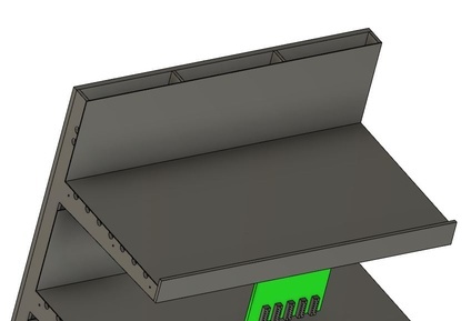
The E-members are stabilized by horizontal deck plates and vertical backdrop plates of 5 mm luan that interlock to constrain all degrees of freedom.
All of the pieces are glued together and secured with 18ga brads.
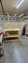
The first module took about 1000 hours to design, 10 hours to program and cut, but just under 2 hours to assemble. The only tools and supplies required for assembly are a tape measure, square, 4ft level (mostly for scribing lines), wood glue/brush and brads/nailer. We also had to make a simple 1" spacer block to set all of facia plates at the proper height. The CNC-cut interlocking plates worked brilliantly to self-square the assembly. we only needed the tape measure to verify it was not racked and to strike nailing lines since the E-members are mostly hidden.
|
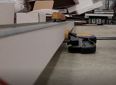
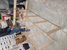
After the glue dried on the prototype, we stood it up to test rigidity. Since the layout gets bumped and trains are easily derailed, the concept had to be rock solid.
Well... it wasn't. The darn thing was a diving board. I was immediately overcome with visions of 727-Zephyrs and Airbus E-units.
Did I mention B1 is an engineer too? We immediately went to work to solve the issue. B1 leveraged the power of our CAD program, Autodesk Fusion 360, to run some "light" FEAs and discovered all of the flex was occurring at the deck arm intersection with the vertical member.
|
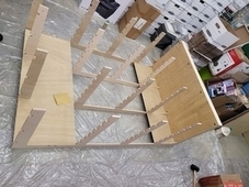
B1 suggested a quick and easy solution to the problem would be to add a backing plate to the entire frame effectively making the entire structure a series of box beams. Brilliant! We added a 3/4 inch plywood sheet to back and it helped immensely. It still had just enough spring though that I could not sign off on the design.
|
As we studied the problem, it became obvious I had missed one key flaw in the design.
The weakest/thinnest cross section of the E-member is right at the base at the intersection of the vertical and horizontal beams even with the intentional gusset I had included. Studying the problem further, I discovered I actually amplified it inadvertently when I added a location notch to simplify the assembly of the leveling legs.
We grabbed a couple of scraps of woods and secured them to the ends of the module between the base and the first deck.
As Bob Seger liked to sing... "Like A Rock". Problem solved, solid and stable.
|
The layout measures 205" x 218" long in a basic L configuration and is 72" tall. Deck heights are set at 18", 37" and 55" respectively, floor to track base and are 24" deep. The two helix modules measure 48" x 48" each.
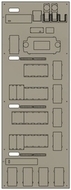
The layout consists of 9 track modules plus a control module. The track modules include:
1x Helix Module A
1x Helix Module B
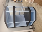
1x Corner Module
1x 24" Straight Module
1x 36" Straight Module
4x 48" Straight Module
|
Photo Album Gallery Place Holder - Please wait while the Photo Album loads.
If the album does not show, please refresh the page to try again.
|
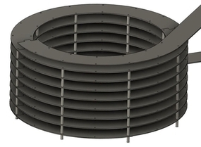
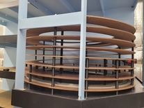
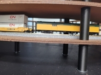
Each helix has 7.75 turns at 2.38 inch spacing between turns which leaves about 1/2 inch clearance to the tallest cars (Kato Maxi-Stacks) I "might" run. The radius is designed to fit Kato 20-185 super-elevated double track UNITRACK having 18-7/8" + 17-5/8" radii respectively.
By my math, the final grades calculate out to be around 2.00% and 2.14% respectively.
I know the clearance is tight and I may regret that some day but absolute minimum grade was my first and only consideration. I like to run long trains and this is the Achilles heel of the layout.
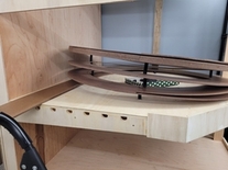
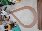
The helix structures are fabricated from 1/8" masonite sheet. The design features 2 plys of 180 degree sections offset and laminated at 90 degree intervals to create a rigid base with smooth assembly joints. The structures also feature fabricated lead ins and lead outs for smooth transition from flat to grade.
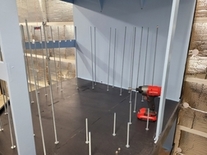
Deck separation is achieved using ultra-precise, 3D printed spacers clamped together and to a 1/2 inch thick plywood base using 1/4 inch all-thread rod. I added some extra mounting holes for additional spacers up front in case the decks start to sag over time. The extra holes are free so why not...
|
Pictures of helix concepts, sizing and testing...
|
Photo Album Gallery Place Holder - Please wait while the Photo Album loads.
If the album does not show, please refresh the page to try again.
|
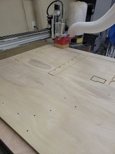
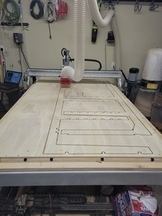
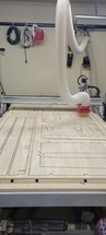
Fabrication of the first prototype pieces.
|
Photo Album Gallery Place Holder - Please wait while the Photo Album loads.
If the album does not show, please refresh the page to try again.
|
Construction of the first prototype.
|
Photo Album Gallery Place Holder - Please wait while the Photo Album loads.
If the album does not show, please refresh the page to try again.
|
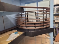
Construction of the Helix and Helix Modules.
|
Photo Album Gallery Place Holder - Please wait while the Photo Album loads.
If the album does not show, please refresh the page to try again.
|
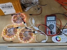
LED Lighting Installation
|
Photo Album Gallery Place Holder - Please wait while the Photo Album loads.
If the album does not show, please refresh the page to try again.
|
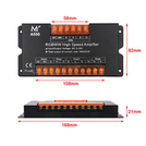
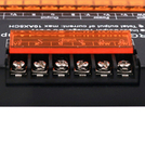
The key to the LED lighting are the Amplifier modules.
|
Photo Album Gallery Place Holder - Please wait while the Photo Album loads.
If the album does not show, please refresh the page to try again.
|
Developing the LED lighting plan for power distribution and BOM planning.
|
Wiring and DCC Installation
|
Developing the power distribution map and BOM planning.
|
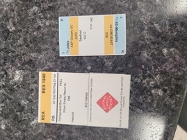
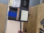
Car cards, waybills, and all of the accoutrements.
|
Photo Album Gallery Place Holder - Please wait while the Photo Album loads.
If the album does not show, please refresh the page to try again.
|
Download files coming soon...
|
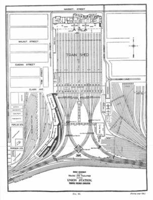
Maybe someday I can expand to Phase 2 to include a scaled down model of St. Louis Union Station....
|
|
|