ESU LokSound 73100-73199 Select Direct Micro "Keep-Alive"
|
The following information has been prepared by and is present here with the express written permission of Peter "peteski" Wisniewski.
This info is also posted on the Railwire in https://www.therailwire.net/forum/index.php?topic=44324.0
I want extend a special word of gratitude and appreciation to "peteski" for allowing me to use this information here.
I started to do something similar. I saw his work and asked why? How could I possibly add anything more to this!
Great job man.
Thanks for providing this info for use by all SBS4DCC patrons.
|
There are some limitations to the platform this site is built on, one being the ability to enlarge and zoom in on images.
Since a picture is worth a thousand words...
|
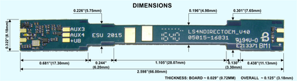
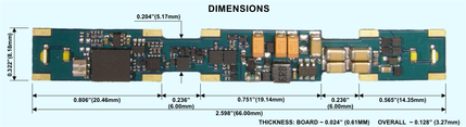
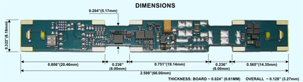
ESU 73100 LokSound Select Direct Micro NMRA DCC Sound Decoder Drop-In for Pre-2016 IRC Locos
|
Judging by the info imprinted on the circuit board (the part number and the date) this decoder is a precursor of the 73199. The date seems to indicate that it was designed in 2015 (73199 shows date of 2016). So even though the 73199 was introduced first (originally factory installed in Intermountain SD40-2, then made available as a separate item), the 73100 appears to have been designed first, but made available only after 73199 was released.
|
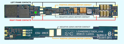
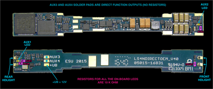
There have been some questions about the motor hookup pads. While the decoder's diagram shown on the paper insert included in the decoder's packaging explains the chassis connections and the bottom motor hookup pads, there is no mention of the motor hookup pads on the top side of the decoder. The above diagram clarifies the purpose of all the pads.
|
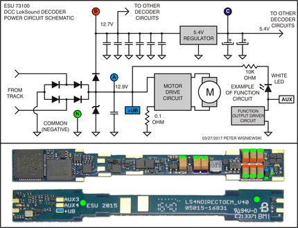
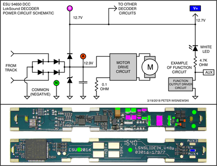
For those who are interested I also drew a partial schematic diagram of this decoder. This decoder's design is different than the 73199. While it also has a power supply circuit with 3 voltage stages, in this decoder the common positive ("blue" or +UB) voltage is now a full 12V supplied from the 1st stage. Stage 1:
Raw rectified track voltage (marked "A" or LIGHT BLUE on the diagram). This stage supplies power to the motor driver circuit and to the next voltage stage (described below). This is where one of the Super-Cap-based keep-alive circuits could be installed to keep both, the decoder's electronics, and the motor running during power dropouts. This stage includes what looks like a Zener diode (for over-voltage protection?) and a very small ceramic capacitor (probably less than 1uF in value, to shunt any voltage spikes coming from the track). Also unlike in the 73199 (and more like a typical decoder), this stage also supplies the "blue wire" (+UB) common positive voltage for all the AUX function outputs. Stage 2:
(marked "B" or RED on the diagram). The voltage from stage 1 is passed through a diode (same type of diode as used in the rectifier) to enter stage 2. This stage has 6 multilayer ceramic caps used as a small stay-alive circuit (totaling probably around 200uF, but since they are unmarked I don't know their exact value). The voltage from this stage is then supplied to stage 3, and probably to few other circuits on the decoder (I didn't do a thorough trace to check what else is powered from this stage). As shown on the diagram, the voltage in this stage is just few tenths lower than the raw rectified voltage of stage 1. Stage 3:
(marked as "C" or DARK BLUE on the diagram). Voltage from stage 2 is supplied to a 5.4V regulator which produces the stage 3 voltage. There are couple of 100uF tantalum caps in this stage to act as a filter/keep-alive. This stage provides power to most of the decoder's circuitry, including the audio amplifier. There are also other voltages derived from 5.4V. Those lower voltages then power the "brains" of the decoder (the microcontroller and the Flash memory chip), and other internal circuits. Unlike in the 73199 the voltage from this stage is *NOT* used as the common positive for all the on-board AUX functions. The tantalum caps in stage 3 (200uF total) do provide minimal protection from short-duration power dropouts, and there is around 200uF worth of capacitors in stage 2, so we can't really say that the decoder has no stay-alives. But all of this results in an absolute bare minimum of the stay-alive capacitance.
Ground (common) of the decoder is marked on the diagram as "N" or GREEN.
|
Where to attach stay-alive capacitors, or a keep-alive SuperCap module?
|
The bottom part of the diagram above shows both sides of the decoder with color-coded locations of where the external caps can be connected. The green circles indicate that the large copper areas are all connected to ground (common).
A capacitor, or a bank of capacitors, can be installed with its negative lead attached to any of the green marked areas or component pads. The positive lead can be connected up to any of the light-blue marked pads (for stage1), or red marked pads (for stage 2). While I also show a pads for stage 3 (dark-blue marked pads), I do not think that any additional caps installed in stage 3 will be helpful.
A true SuperCap-based keep-alive circuit (hundreds of thousands of micro Farads with its built-in ancillary circuitry to limit the charging current and voltage) should be connected to green and light-blue marked pads of the decoder. If added there, it will power the decoder's electronics, motor and the function outputs. On this decoder this is actually the optimal place for hooking up both, a large-capacitance keep-alive module or a smaller bank of capacitors. It is also the easiest hookup location since the +UB pad can be used for the positive side.
If the additional caps are less than 1000uF in total capacitance then they could be attached to the green and red marked pads of the decoder. Since the power-hungry motor is not powered from this stage, the stay-alive cap will supply power just to the decoder's electronics for a longer period of time. Hopefully the flywheels would keep the loco coasting through the intermittent contact spot, while the decoder keeps on running and producing its sounds. Of course, any modification to the decoder are done at your own risk - it is highly miniaturized and delicate.
|
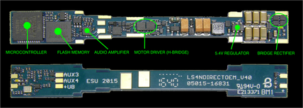
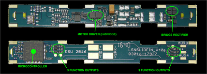
For those interested in more details, here are the locations of some of the decoder's main components. I found it interesting that the rectifier diodes used in this decoder have a very low forward voltage drop (only 0.2V). But I only tested it with minimal load so the voltage drop will most likely increase as the current draw increases. Still, they are probably Shottky diodes with the average voltage drop of around 0.5V or less.
|
MAP OF THE FUNCTION OUTPUTS AND THEIR SOLDER PADS
|
The above picture is self explanatory. All of the on-board LEDs (including the headlight LEDs which are not installed) have a series 10K ohm resistor included on the decoder. That is a fairly high value which results in roughly about 1mA of current passing through the LED, but the LEDs still glow fairly brightly. If someone wants to simply relocate the on-board LEDs while still using the on-board 10K ohm resistors, then unsolder the SMD LED from the PC board, then solder the wire lead extensions to the LED pads. The LED polarity (anode or positive [A] and cathode or negative [C]) is indicated in the picture. The on-board LED current-limiting resistors are installed on the anode (positive) side of the LEDs. Unfortunately those tiny SMD 0402 LEDs (0.040" x 0.020" footprint) with lots of small components surrounding them will be difficult to unsolder. Instead of calling their outputs "functions" like most DCC manufacturers do, ESU calls them "AUX" outputs. This is likely due to the fact that all these outputs can easily be mapped to any DCC function. The mapping feature on the ESU decoders is much more flexible than on most typical DCC decoders from American manufacturers. I highly recommend thoroughly reading through the ESU decoder manual to get familiar with the AUX output mappings. While the mapping can be done by individually programming a bunch of CVs on DCC system's programming track, this task is made *MUCH* easier using the ESU's LokProgrammer interface and software.
|
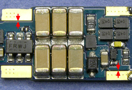
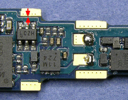
As I mentioned earlier, going by the year imprinted on the ESU circuit boards, the 73100 was designed a year earlier than the 73199. I see few things that IMO are not optimal on the 73100, and I also see that they were addressed on 73199. The first shortcoming I see is that the chassis contact pads are only present on the one side (the top) of the decoder board. The chassis contact tabs are designed in a way which makes contact with the top and bottom of the decoder board. While not a huge problem, having the pads on both sides improves the board-to-chassis contact reliability. This has been addressed on the 73199 as it has metal pads on both sides of the board. Also relating to the chassis contact tabs is the narrow width of most of the chassis pads, and the closeness to the decoder's ground plane to the inner edges of those pads. Here are couple of photos showing what I'm describing.
|
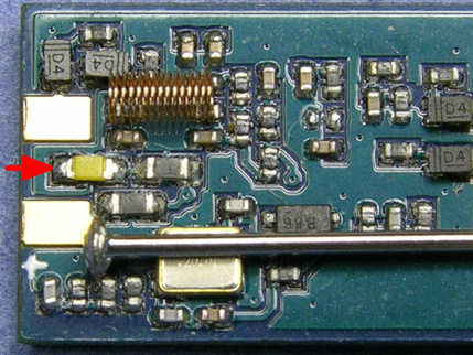
The arrows show how small the gap is between there the chassis' contact pad inner edge and the edge of the decoder's ground plane. Since this is a universal-fit decoder (not designed for a specific model) it might be possible that some particular model's chassis has its contact tabs which are deeper than the width of the contact pad on the decoder and they can protrude deeper into the decoder possibly crossing over to the ground plane. While the ground plane has the green solder mask coating applied over it, there is a possibility that the chassis tab can scrape that coating and contact the ground (which would likely result in a damage to the decoder's circuitry). This is something to watch for when installing these decoders. Another item which I don't think is optimal is the way ESU handled the AUX (function) outputs. While the front and rear headlights and the AUX 3 and 4 outputs have easily accessible solder pads, AUX 1 and 2 are hardwired directly to the tiny SMD 0402 LEDs on the decoder. Most modelers who will want to utilize AUX 1 and 2 outputs in their models will find those on-decoder LEDs not in optimal locations for their specific model. Items such as ditch lights, Mars light, rotary beacons or strobes will require LEDs mounted remotely.
|
Here's a photo showing the magnified area of one of the AUX LEDs. For size reference, included in the photos, is also a common sewing pin (it is 0.020" in diameter) and a tiny Micro Trains coupler spring. The LED itself (pointed to by the red arrow) has a footprint of only 0.040" X 0.020" and the solder pads under it are even smaller. The LED is also closely surrounded by more tiny components. Most modelers utilizing this decoder in their models will have a hard time cleanly removing that LED to gain access to the small AUX pads. Since this is the only way to gain access to the AUX 1 and 2 outputs, this can be a problem. This design issue also appears to have been addressed in the 73199 since all of that decoder's AUX outputs are available on a decent size solder pads. As I see it, this decoder, even with some of its shortcomings, will be useful in some of the custom installs in narrow-hood models.
|
ESU 73199 LokSound Select Direct Micro OEM NMRA DCC Sound
Decoder Drop-In for Post-2016 IRC Locos
|
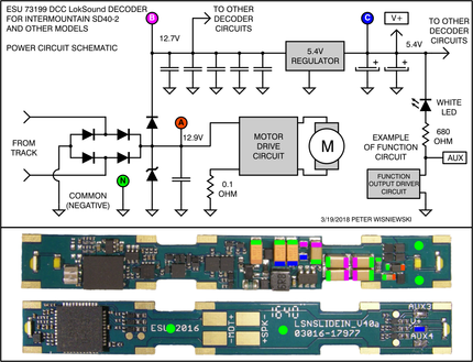
For those who are interested I drew a partial schematic diagram of the decoder. This decoder's design is different and more complex from other sound decoders I have dealt with in the past. It has a power supply circuit with 3 voltage stages where a stay-alive caps or keep-alive module could be hooked up. Stage 1: Raw rectified track voltage (marked "A" or RED on the diagram). This stage supplies power to the motor driver circuit, and to the next voltage stage (described below). This is where one of the SuperCap-based keep-alive circuits could be installed to keep both, the decoder's electronics, and the motor running during power dropouts. This stage includes what looks like a Zener diode (for over-voltage protection?) and a very small ceramic capacitor (probably less than 1uF in value, to shunt any voltage spikes coming from the track). Stage 2: (marked "B" or PURPLE on the diagram). The voltage from stage 1 is passed through a diode (same type of diode as used in the rectifier) to become stage 2. This stage has five multilayer ceramic caps used as a small stay-alive circuit (totaling probably around 250uF, but since they are unmarked I don't know their exact value). The voltage from this stage is then supplied to stage 3, and probably to few other circuits on the decoder (I didn't do a thorough trace to check what else is powered from this stage). As shown on the diagram, the voltage in this stage is just few tenths lower than the raw rectified voltage of stage 1.
Stage 3: (marked as "C" or BLUE on the diagram). Voltage from stage 2 is supplied to a 5.4V regulator which produces the stage 3 voltage. There are two 100uF tantalum caps in this stage to act as a filter/keep-alive. This stage supplies power to most of the decoder's circuitry, including the audio amplifier. There are also couple more voltages derived from 5.4V. One is 5.1V (not sure where it is used) and also 3V, which powers the "brains" of the decoder (the microcontroller and the Flash memory chip which has the sound files). Voltage from this stage is also used as the common positive for all the decoder's AUX functions (including the V+ solder pad). The designers of this decoder decided to use the 5.4V as the BLUE common-positive (instead of the usual rectified 12V track voltage used on majority of other decoders). The tantalum caps in stage 3 (200uF total) do provide minimal protection from short-duration power dropouts, and there is also around 250uF worth of capacitors in stage 2, so we can't really say that the decoder has no stay-alives. But all those capacitors provide bare minimum of the stay-alive capacitance. Ground (common) of the decoder is marked on the diagram as "N".
|
Where to attach stay-alive capacitors, or a keep-alive SuperCap module?
|
The bottom part of the diagram above shows both sides of the decoder with color-coded locations of where the external caps can be installed. The green circles indicate that the large copper areas are all connected to ground (common). A capacitor, or a bank of capacitors, can be installed with its negative lead attached to any of the green marked areas or component pads. The positive lead can be hooked up to any of the red marked pads (for stage 1), or purple marked pads (for stage 2). While I also show hookup locations for stage 3 (blue marked pads), I do not think that any additional caps installed in stage 3 will be helpful in keeping the sound uninterrupted and the model running. A true SuperCap-based keep-alive circuit (hundreds of thousands of micro Farads with its built-in ancillary circuitry to limit the charging current and voltage) should be attached to green and red marked pads of the decoder. If installed there, it will power the decoder's electronics, the motor, and the function outputs. Since the RED pads on the decoder are very small and close to other components, one must be super-careful not to damage any components while adding the keep-alive circuit. If the additional caps will be less than 1000uF in total capacitance then my recommendation is to attach them to the green and purple marked pads of the decoder. Since the power-hungry motor is not powered from that stage, the keep-alive cap will supply power to the decoder's circuitry for a longer time. Hopefully the flywheels will keep the loco coasting through the intermittent contact spot while the decoder keeps on running and producing sounds. Of course, any modification to the decoder are done at your own risk - it is highly miniaturized and delicate. For those interested in more details, here are the locations of some of the decoder's main components.
|
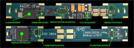
I found it interesting that the rectifier diodes used in this decoder have a very low forward voltage drop (only 0.2V). But I only tested it with minimal load so the voltage drop will most likely increase as the current draw increases. Still, they are probably Shottky diodes with the average voltage drop of around 0.5V or less.
|
MAP OF THE FUNCTION OUTPUTS AND THEIR SOLDER PADS
|
The above picture is self explanatory. If someone wants to simply relocate the on-board LEDs while still using the on-board 680 ohm resistors, then unsolder the SMD LED from the PC board, then solder the wire lead extensions to the LED pads. The LED polarity (anode or positive [A] and cathode or negative [C]) is indicated in the picture. Instead of calling those outputs "functions" like most DCC manufacturers do, ESU calls them "AUX" outputs. This is likely due to the fact that all these outputs can easily be mapped to any DCC function. The output mapping feature on the ESU decoders is much more flexible than on most typical DCC decoders from American manufacturers. I highly recommend thoroughly reading through the ESU decoder manual to get familiar with the AUX output mappings. While the mapping can be done by individually programming a bunch of CVs on DCC system's programming track, this task is made *MUCH* easier using the ESU's LokProgrammer interface and software.
|
ESU 54650 LokPilot V4.0 Direct Micro OEM NMRA DCC Decoder Drop-In for Post-2016 IRC Locos
|
This decoder is basically a "dumbed down" 73199 Lok Sound decoder. ESU used the 73199 circuit board, but didn't install any of the sound-generating components. They also used a microcontroller chip with less "horsepower". However, this decoder's non-sound features are fully compatible to the 73199.
|
Just like for the 73199, I created a diagram of the power supply. Comparing it to the 73199 you will notice that the power supply section is much simplified. There are only 2 stages in the power supply. There are no stay-alive capacitors in either of the power supply stages. Stage 1: Raw rectified track voltage (marked "A" or RED on the diagram). This stage supplies power to the motor driver circuit, and to the stage 2 (described below). This is where one of the SuperCap-based keep-alive circuits could be installed to keep both, the decoder's electronics, and the motor running during power dropouts. This stage includes what looks like a Zener diode (for over-voltage protection?) and a very small ceramic capacitor (probably less than 1uF in value, to shunt any voltage spikes coming from the track). Stage 2: (marked "B" or PURPLE on the diagram). Voltage from stage 1 is passed through a diode (same type of diode as used in the rectifier) to become stage 2. Voltage from this stage is used for all of the decoder's circuitry. This stage also provides the V+ common positive voltage for the decoder's AUX functions, a.k.a. on other decoders as the "blue" lead. This design is more in line with the general decoder design where the "blue" voltage is around 12V, and unlike the 73199 decoders V+ voltage which is only 5.4V. There is also a lone 100uF tantalum capacitor on the decoder, but it is used in the low voltage power circuit. It is not a typical stay-alive capacitor. Ground (common) of the decoder is marked on the diagram as "N".
|
Where to attach stay-alive capacitors, or a keep-alive SuperCap module?
|
The bottom part of the diagram above shows both sides of the decoder with color-coded locations of where the external caps can be installed. The green circles indicate that the large copper areas are all connected to ground (common). A capacitor, or a bank of capacitors, can be installed with its negative lead attached to any of the green marked areas or component pads. The positive lead can be hooked up to any of the red marked pads (for stage 1), or purple marked pads (for stage 2). In this decoder the V+ pad is also connected to the purple circuit. A true SuperCap-based keep-alive circuit (hundreds of thousands of micro Farads with its built-in ancillary circuitry to limit the charging current and voltage) should be attached to green and red marked pads of the decoder. If placed there, it will power the decoder's electronics, the motor, and the function outputs. Since the RED pads on the decoder are very small and close to other components, one must be super-careful not to damage any components while adding the keep-alive circuit. If the additional caps will be less than 1000uF in total capacitance then my recommendation is to attach them to the green and purple marked pads of the decoder. Since the power-hungry motor is not powered from that stage, the keep-alive cap will supply power to the decoder for a longer time. Hopefully the flywheels will keep the loco coasting through the intermittent contact spot while the decoder keeps on running and generating sounds. Of course, any modification to the decoder are done at your own risk - it is highly miniaturized and delicate. For those interested in more details, here are the locations of some of the decoder's main components.
|
I found it interesting that the rectifier diodes used in this decoder have a very low forward voltage drop (only 0.2V). But I only tested it with minimal load so the voltage drop will most likely increase as the current draw increases. Still, they are probably Shottky diodes with the average voltage drop of around 0.5V or less.
|
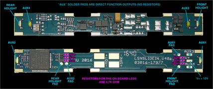
MAP OF THE FUNCTION OUTPUTS AND THEIR SOLDER PADS
|
The above picture is self explanatory. If someone wants to simply relocate the on-board LEDs while still using the on-board 4.7K ohm resistors, then just unsolder the SMD LED from the PC board, then solder the wire lead extensions to the LED pads. The LED polarity (anode or positive [A] and cathode or negative [C]) is indicated in the picture. Instead of calling those outputs "functions" like most DCC manufacturers do, ESU calls them "AUX" outputs. This is likely due to the fact that all these outputs can easily be mapped to any DCC function. The mapping feature on the ESU decoders is much more flexible than on most typical DCC decoders from American manufacturers. I highly recommend thoroughly reading through the ESU decoder manual to get familiar with the AUX output mappings. While the mapping can be done by individually programming a bunch of CVs on DCC system's programming track, this task is made *MUCH* easier using the ESU's LokProgrammer interface and software.
|
Setting CV315 - Disable Aux6
|
It is necessary to disable Aux6 (CV315 = 0) in the Standard model decoders in order to use the Keep-Alive function.
If Aux6 is enabled, the keep-alive will be effectively turned off.
In LokProgrammer, V4.0 projects display a warning and link that when clicked, automatically sets CV315 = 0, thereby disabling Aux6.
Select projects do not display the warning or link but the CV value and results are the same.
|
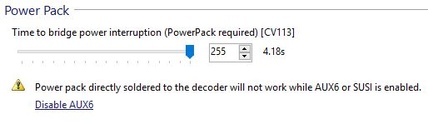
Setting CV113 - The Keep-Alive Timer
|
All ESU LokSound V4.0 and Select models incorporate a timer to determine the maximum amount of time a Keep-Alive Device can supply power to the circuit.
Essentially, the time limits the amount of time a Keep-Alive Device can supply power to the circuit without receiving a packet of data from the command station.
I won't pretend to know every reason for needing the timer but the most obvious to me is so that the locomotive won't continue endlessly in a true power outage event.
The default setting in most files is about .25 seconds. The available range is 0 to 4 seconds.
CV113 = (0 - 255) where 0 is no keep-alive power and 255 is about 4 seconds of keep-alive power.
Be sure to test this to determine the value that works best for your application.
Here is a brief video demonstration of how CV113 works.
|
|
|