NEM651 Connector - Half Wave Rectification
|
Occasionally a customer will purchase a decoder that uses the NEM651 6-pin interface and will ask why it doesn't have a blue wire or where they are supposed to connect the blue wire.
To be sure, this is not a mistake. The NEM651 6-pin interface does not include the "blue" or common +V DC wire by design.
Some models of decoders like the TCS EUN651 do not have a "blue" common wire. Models like the ESU 54685 LokPilot V4.0 Micro do have a "blue" common but it is just a loose wire.
A good place to start is a quick look at the standard.
|
The NEM651 6-pin Standard
|
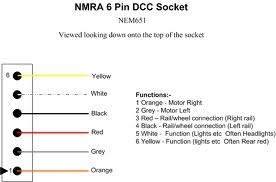 |
| NEM651 Pinout |
|
|
 |
| NEM651 Connector with Wires |
|
|
OK, Great... Where's The Blue Wire...
|
The bridge circuit converts the DCC waveform (similar to an AC waveform) to DC to use for powering the motor and lights.
The blue wire is effectively the positive output of the bridge and is called the Common. It is better termed the rectified DC common. The output voltage of the blue wire is typically track power minus voltage drop across the bridge. The DC Common is generally used to power LEDs and other accessories.
The NEM651 standard omits the DC common (blue wire) connection as part of the connector. You can find the standard here.
http://www.nmra.org/sites/default/files/standards/sandrp/pdf/S-9.1.1_Connectors_2013.07.pdf
Models that utilize this connector typically use whats called half wave rectification to power the LED lights.
Here is more info on the topic written better than I could explain.
http://www.allaboutcircuits.com/vol_3/chpt_3/4.html
In our model trains, half wave rectification works by using the only half of the DCC power wave. The anode, or positive side, of the LED is connected directly to one side of the rail power pickup (think red or black wire) or frame half on split frame designs. The LED illuminates on the positive side of the wave and turns off on the negative side of the wave
Advantages... less wires and smaller connector.
Disadvantages... shorter LED life from constant power cycling and half wave "flicker".
Some decoders, specifically the ESU LokPilots and LokSounds ship with a blue wire attached to the decoder from the the factory. Some decoders, like a Zimo, have a solder pad to add the blue wire if you need it for your project. Other decoders, like the TCS EUN651 or Digitax DZ126IN may have a solder pad to connect to but it is not implicit in the respective instruction sheets.
Referring specifically to the ESU LokPilot Micro, they use the same circuit board for every model of their micro decoder and only change the interface connector. I suspect that the blue wire is attached prior to the connector so every model has it. I would have to dig deeper to confirm that though and it is not critical to this conversation. It is required for the NEM652 model and is needed if doing a hardwired installation.
Referring back to the disadvantages, you may or may not detect the half wave flicker. The DCC signals are 8 to 10 KiloHertz. If you think you see the light in your 6-pin decodered model pulsing, well, it is. Can a human eye truly detect it, I dunno. You can eliminate any pulsing completely by connecting the anode of the LED to the blue wire instead of the frame.
The first circuit of nearly every decoder is a bridge rectifier or individual diodes arranged to create a diode bridge.
The bridge circuit converts the DCC waveform (similar to an AC waveform) to DC to use for powering the motor and lights.
This is also called full-wave rectification. I will let you investigate that on your own.
The blue wire is effectively the positive output of the bridge and is called the Common. It is better termed the rectified DC common. The output voltage of the blue wire is typically track power minus voltage drop across the bridge. The DC Common is generally used to power LEDs and other accessories.
The NEM651 standard omits the DC common (blue wire) connection as part of the connector.
Models that utilize this connector typically use whats called half wave rectification to power the LED lights.
Here is even more info on the topic written better than I could explain.
|
Model Trains And Half Wave Rectification
|
In our model trains, half wave rectification works by using the only half of the DCC power wave. The anode, or positive side, of the LED is connected directly to one side of the rail power pickup (think red or black wire) or frame half on split frame designs. The LED illuminates on the positive side of the wave and turns off on the negative side of the wave. Here is a wiring diagram that illustrates how the decoder is connected and how the LED lighting gets power.
|
 |
| Model Train Wiring With NEM651 Connector And Half Wave Rectification |
|
|
Some decoders, specifically the ESU LokPilot Micros and LokSounds ship with a blue wire attached to the decoder from the the factory.
Some decoders, like a Zimo MX622N, have a solder pad to add the blue wire if you need it for your project.
Other decoders, like the TCS EUN651 or Digitax DZ126IN may have a solder pad to connect to but it is not implicit in the respective instruction sheets.
Referring specifically to the ESU LokPilot Micros, they use the same circuit board for every model of their micro decoder and only change the interface connector.
I suspect that the blue wire is attached prior to the connector so every model has it.
I would have to dig deeper to confirm that though and it is not critical to this conversation.
It is required for the NEM652 model and is needed if doing a hardwired installation.
|
OK, Great... Why Do I Need The Blue Wire...
|
Do you really need the blue wire?
Well technically, no.
When doing an N Scale installation, this offers the advantage of less wires and a smaller connector. It is important to note that you can use half wave rectification in any installation, in any scale, even if the decoder has a blue wire.
There is one significant disadvantage however called half wave "flicker".
You may or may not detect the half wave flicker with the naked eye.
The DCC signals are 8 to 10 KiloHertz or about .0001 seconds per period.
Said another way, it "flickers" about 10,000 time per second.
If you think you see the light in your 6-pin decodered model pulsing, well, it is.
Can a human eye truly detect it, I dunno.
The problem is greatly exaggerated however when the LED light is dimmed using adjustable output brightness or Rule 17 dimming or similar function effects.
Since most dimming functions use a form of PWM to turn the light on and off rapidly, the "flicker" is now compounded by modulating only half of the wave.
That's enough for me to use full wave rectification and connect LEDs to the rectified DC common, a.k.a. the blue wire, whenever possible.
|
Digitrax Transponding and Half Wave Rectification
|
When you install a wired transponder equipped decoder, you should also install a load resistor of between 270 ohms & 470 ohms between the blue and white decoder outputs. If you are using a board decoder, like Digitrax DN149K2, the resistor may already be installed on the decoder. Digitrax transponder current pulse generation uses the F0 decoder function output that is also used for the forward light function. Transponding will not affect the operation of the forward light but you may see a slight glow when the light is turned off because of the way transponding works. If you are running zones where the average current draw is more than 3 amps, you can connect an additional 100 ohm 1/8 watt resistor in series with a 0.1uF ceramic capacitor across the white and blue decoder outputs. Note: If the resistor is not connected between the blue & white outputs, then the locomotive will transpond in only one orientation on the track
When you install a wired transponder equipped decoder, you shouldalso install a load resistor of between 270 ohms & 470 ohmsbetween the blue and white decoder outputs. If you are using a boarddecoder, like Digitrax DN149K2, the resistor may already beinstalled on the decoder. Digitrax transponder current pulse generationuses the F0 decoder function output that is also used for the forwardlight function. Transponding will not affect the operation of theforward light but you may see a slight glow when the light is turnedoff because of the way transponding works. If you are runningzones where the average current draw is more than 3 amps, you canconnect an additional 100 ohm 1/8 watt resistor in series with a0.1uF ceramic capacitor across the white and blue decoder outputs.Note: If the resistor is not connected between the blue & white outputs,then the locomotive will transpond in only one orientation on thetrack
If you plan to use Digitrax Transponding for feedback, be aware that you may be able to use half wave rectification.
From the Digitrax Decoder manual...
When you install a wired transponder equipped decoder, you should also install a load resistor of between 270 ohms & 470 ohms between the blue and white decoder outputs.
If you are using a board decoder, like Digitrax DN149K2, the resistor may already be installed on the decoder.
Digitrax transponder current pulse generation uses the F0 decoder function output that is also used for the forward light function.
Transponding will not affect the operation of the forward light but you may see a slight glow when the light is turned off because of the way transponding works.
If you are running zones where the average current draw is more than 3 amps, you can connect an additional 100 ohm 1/8 watt resistor in series with a 0.1uF ceramic capacitor across the white and blue decoder outputs.
Note: If the resistor is not connected between the blue & white outputs, then the locomotive will transpond in only one orientation on the track.
|
Here is an alternate wiring schematic using the NEM651 connector that incorporates diodes to supply rectified DC voltage for the lighting functions.
|
 |
| Model Train Wiring With NEM651 Connector and Full Wave Rectification |
|
|
Half Wave Rectification and LED Life
|
Using half wave rectification will not shorten LED life from constant power cycling.
From one of my suppliers web-site...
"Unlike incandescent and fluorescent lighting which will fail sooner when switched on and off more often, LED lighting is unaffected by how often it is switched on and off."
"The life span of an LED is vastly longer than that of incandescent, fluorescent or HID lamp sources, generally lasting 50,000 hours or longer. Although the LED never really burns out, product life span is measured by lumen depreciation."
"The Illuminating Engineering Society's (IES) current standard for calculating the life of an LED as the point at which the LED reaches 30 percent lumen depreciation."
"Remember, a 100,000-hour rating is not equivalent to lamp life rating. LED life is rated where it has reached 30 percent lumen depreciation. At 100,000 hours an LED would still be operating, but at a decreased lumen output."
I have read elsewhere that cycling can reduce life by a small percentage. In relative terms if the LED operates 24 hours per day, expected life is 13 years.
If the cycling reduced life by 10% it would still have a 90,000 hour or 10 year life expectancy.
If you are running model trains 10 years, 24 hours per day... LED life is probably not your greatest issue.
shorter LED life from constant power cycling and
You can eliminate any pulsing completely by connecting the anode of the LED to the blue wire instead of the frame.
I mis-spoke or at least gave that point more importance than it deserved.
From one of my suppliers web-site...
"Unlike incandescent and fluorescent lighting which will fail sooner when switched on and off more often, LED lighting is unaffected by how often it is switched on and off."
"The life span of an LED is vastly longer than that of incandescent, fluorescent or HID lamp sources, generally lasting 50,000 hours or longer. Although the LED never really burns out, product life span is measured by lumen depreciation."
"The Illuminating Engineering Society's (IES) current standard for calculating the life of an LED as the point at which the LED reaches 30 percent lumen depreciation."
"Remember, a 100,000-hour rating is not equivalent to lamp life rating. LED life is rated where it has reached 30 percent lumen depreciation. At 100,000 hours an LED would still be operating, but at a decreased lumen output."
I have read elsewhere that cycling can reduce life by a small percentage. In relative terms if the LED operates 24 hours per day, expected life is 13 years. If the cycling reduced life by 10% it would still have a 90,000 hour or 10 year life expectancy.
If you are running model trains 10 years, 24 hours per day... LED life is probably not your greatest issue.
Thanks for pointing that out.
As I write this correction, I ask what then are the disadvantages of using half wave rectification in installs since LED life is not significantly affected and flicker is a matter of perception.
I can't really think of much.
Higher operating voltage... but that has no impact if the resistor is size properly.
Does it increase the risk of damage to the decoder from a short circuit since you introduce a direct path backwards though the circuit? I dunno...
Any one else care to weigh in?
From an N Scale decoder installers perspective, one less wire is a huge advantage. I have shied away from the technique only because I didn't like eliminating the rectified common. One less wire is one less wire.
Hmmm....
I mis-spoke or at least gave that point more importance than it deserved.
From one of my suppliers web-site...
"Unlike incandescent and fluorescent lighting which will fail sooner when switched on and off more often, LED lighting is unaffected by how often it is switched on and off."
"The life span of an LED is vastly longer than that of incandescent, fluorescent or HID lamp sources, generally lasting 50,000 hours or longer. Although the LED never really burns out, product life span is measured by lumen depreciation."
"The Illuminating Engineering Society's (IES) current standard for calculating the life of an LED as the point at which the LED reaches 30 percent lumen depreciation."
"Remember, a 100,000-hour rating is not equivalent to lamp life rating. LED life is rated where it has reached 30 percent lumen depreciation. At 100,000 hours an LED would still be operating, but at a decreased lumen output."
I have read elsewhere that cycling can reduce life by a small percentage. In relative terms if the LED operates 24 hours per day, expected life is 13 years. If the cycling reduced life by 10% it would still have a 90,000 hour or 10 year life expectancy.
If you are running model trains 10 years, 24 hours per day... LED life is probably not your greatest issue.
Thanks for pointing that out.
|
Be sure to visit the store to see our full line of LED Lighting products today!
|
|
|