Kato N Scale UP FEF-3 4-8-4 Northern ESU LokSound DCC Decoder Installation
|
Streamlined Backshop offers a variety of services including DCC decoder installations.
I have been blessed with more work than I can accomplish and simply don't have time to accept every opportunity I am presented.
One of my favorite proverbs is "give a man a fish and you feed him for a day; teach a man to fish and you feed him for a lifetime".
With these thoughts in mind, I present this information for those who want to give it a go but struggle with the how to.
For this group of modelers, this is how I do it.
The same basic products, tools and techniques can be applied to nearly any model of the same genre so be sure to look at the forest, not just the trees.
Be sure to visit my online train store, www.SBS4DCC.com today where you can purchase this model and everything you will need to complete the decoder installation as described!
|
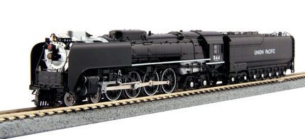
The Kato N Scale UP FEF-3 4-8-4 Northern
|
In December 2014, Kato released the newest model in its line of fine N scale products, the Union Pacific FEF-3 4-8-4 Northern.
The new model offers many innovative features that make it an excellent runner including an isolated coreless motor drive system.
The model can be reasonably labeled as DCC compatible although it was not intentionally designed for sound installations.
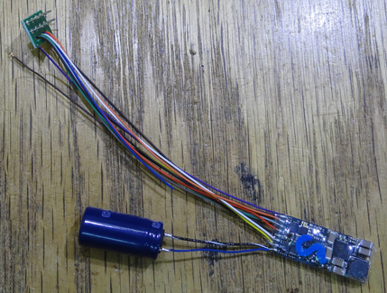
I am using an ESU 73800 LokSound Select Micro DCC sound decoder for this installation because it is small, offers excellent motor control for silky smooth operation, four function outputs, and a great "steamboat" type UP whistle option that compliments the model perfectly.
TCS and Digitrax both offer circuit board replacement "drop-in" decoders for the model but they are not sound decoders.
|
Recommended Tools and Supplies
|
UPDATED MATERIAL LIST AND SOUND FILE
|
There are a few tools and supplies recommended for performing this decoder installation.
Tools:
Soldering Iron Motor Tool
Supplies:
LocTite Go2Glue
LocTite Gel Control Super Glue
Tinning Flux
60/40 Rosin Core Solder
|
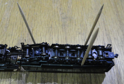
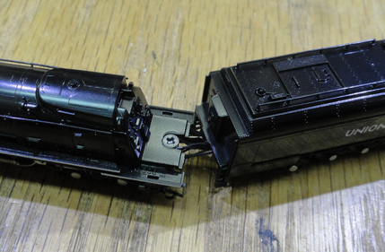
Taking this model apart is very simple.
The tender shell simply snaps on to the floor. Insert a couple of tooth picks in the gap at the boxes near the front truck and slide them to the back. Insert a couple more in the same place is needed and gently lift the floor out of the body shell.
|
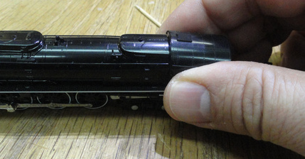
The cab simply snaps onto the boiler shell. Gently grasp the cab sides and lift and pull away from the boiler until the cab comes loose.
|
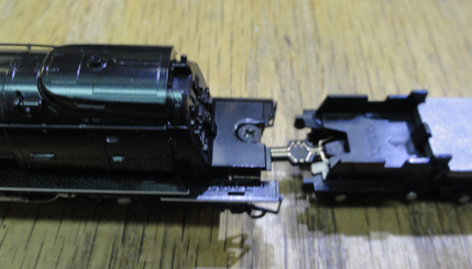
Finally, the boiler shell is held in place with a single screw directly under the cab. Remove the screw and lift the shell off the chassis.
|
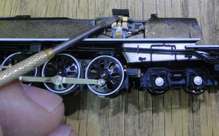
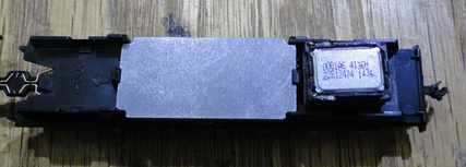
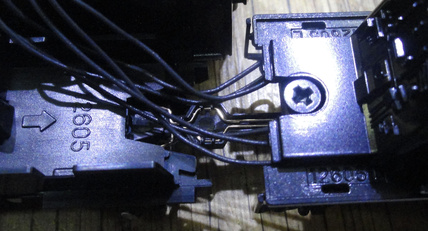
To remove the circuit board, begin by removing the board/motor retaining clip.
|
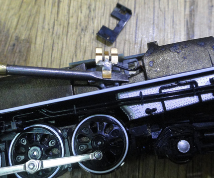
Next, gently lift up on the bottom edge of the motor brush tabs and pull away from the board. Then slide board backwards until the contact pads clear the frame and lift it off the chassis.
|
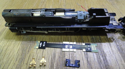
Then remove the motor brush tabs from the motor leads and discard (or save for another rainy day project).
|
Circuit Board Modifications
|
I like to begin my installations by planning the lighting since motor and power pickup are usually pretty straight forward and the lighting usually requires extra time for the glue to dry.
I am using a four function decoder for this project so I am going to illuminate the front headlight, the rear headlight, the cool red mars light mounted above the front headlight, and add simulated firebox flicker.
Since the front headlight is illuminated by LED and Kato went to the trouble of tinting the lens to an acceptable shade that produces a nice warm white, "incandescent" glow, I will just use the LED, circuit board and light pipe as supplied with a few minor modifications.
So, for this model I will need to modify the existing circuit board for use with a DCC decoder.
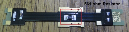
It is important to check the LED resistor supplied with the circuit board to be sure the LED will be safe to use with the higher voltage supplied by DCC systems.
In this case, the board incorporates a 561 ohm resistor which is safe to about 14.5 volts which is near the lower limit for safe operation. For higher voltage systems, replace the LED with a 680 ohm or higher 1206 SMD resistor.
Refer to my page on LED Lighting for more information about this topic.
I like to begin this installation by modifying the circuit board.
Since the front headlight is illuminated by LED and Kato went to the trouble of tinting the lens to an acceptable shade that produces a nice warm white, "incandescent" glow, I will just use the LED, circuit board and light pipe as supplied with a few minor modifications.
|
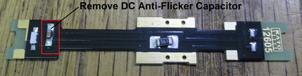
First, I remove the small DC anti-flicker capacitor for the LED from the circuit board.
|
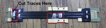
Next, I cut two traces on the board as shown using a motor tool with cutoff wheel or a hobby knife. This isolates the LED circuit from the power pickup circuit.
|
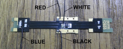
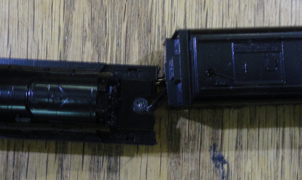
Finally, I attach (4) six-inch leads of black wire at the points shown. Two of the leads are for the headlight and two are for power pickup.
|
It is important to note that you do not have to add the two wires for power pickup.
There are a few options for power pickup with this model since Kato has used a powered drawbar connection and included two-truck pickup in tender.
You could attach wires to the brass strips in the tender or you could connect to both chassis and tender for even better long-term performance.
I have elected to connect to only the chassis pickups since the drivers stay the cleanest, the model has a powered drawbar, and I will be adding a small "keep-alive" capacitor to the decoder.
You can substitute the appropriately colored wire per the NMRA spec but I prefer the look of the black wire since a small portion will be exposed between the cab and tender.
It is handy to mark the wires in some way or else you will have to try to figure out whats what later in the process.
Finally, I attach (4) six-inch leads of black wire at the points shown. Two of the leads are for the headlight and two are for power pickup.
It is important to note that you do not have to add the two wires for power pickup.
There are a few options for power pickup with this model since Kato has used a powered drawbar connection and included two-truck pickup in tender.
You could attach wires to the brass strips in the tender or you could connect to both chassis and tender for even better long-term performance.
I have elected to connect to only the chassis pickups since the drivers stay the cleanest, the model has a powered drawbar, and I will be adding a small "keep-alive" capacitor to the decoder.
You can substitute the appropriately colored wire per the NMRA spec but I prefer the look of the black wire since a small portion will be exposed between the cab and tender.
It is handy to mark the wires in some way or else you will have to try to figure out whats what later in the process.
|
Optional Rear Headlight LED
|
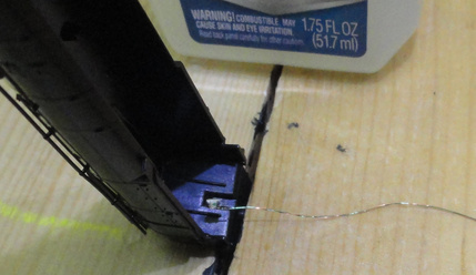
The rear headlight is pretty easy. I begin by test-fitting a SBS4DCC 1206 SMD Warm White Pre-Wired LED placed directly behind the rear light pipe in the tender body shell.
Once I have the wires manipulated so that the LED will lay in place, I encapsulate the LED and light pipe with a few drops of LocTite Go2Glue and set it aside to dry.
|
Optional Firebox Flicker LED
|
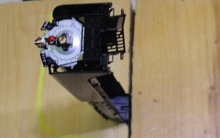
The first step to adding firebox flicker is to figure out how I am going to hold everything in place until the glue is dry.
In this project, I am going to wedge the handy cab floor between two heavy blocks of wood to hold it vertical.
I will add a small piece of double-sided tape to one of the blocks to help hold the LED in place.
|
Next, I add a small hole to backhead where the firebox doors are located.
I drill a #66 hole and clean up any flash with a hobby knife.
|
Then I position the boiler shell in the holding blocks and add a few drops of LocTite Go2Glue to the inside of the boiler shell and lay a SBS4DCC 0603 SMD Red Pre-Wired LED in the puddle so that it covers the hole in the backhead.
I place a heavy object on the it to hold in place until the glue has had time to set up.
|
Once the glue is dried (I like to let it cure for about twenty-four hours), coat the backside of the assembly with Liquid Electrical Tape to insulate the LED from the chassis.
|
As a side note, the LED seems to have plenty of clearance on this install. When adding this upgrade to other models, test fit shell to the boiler and mill out a clearance pocket in the chassis as required to prevent any shorting between the LED and frame.
|
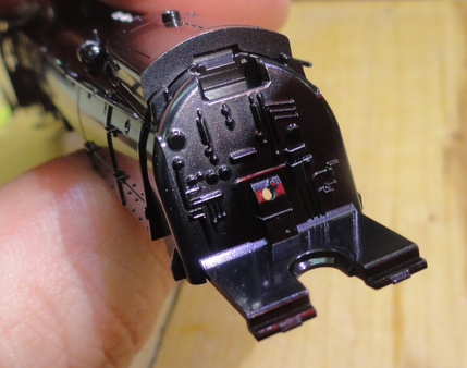
The functioning MARS light is a pretty cool upgrade but pretty aggressive.
This part of the project is not for the faint of heart.
You could use the fourth function for an in-cab light or maybe a dual white/red cab flicker if you want to go down a simpler road.
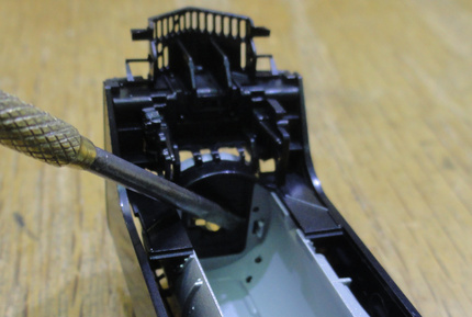
The upgrade begins with dis-assembly of the smokebox door.
The door is held in place by two tiny catch-tabs. Pry the free with small flat-blade screw driver from inside the boiler shell.
|
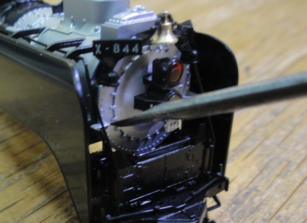
Be especially careful about removing this part.
There are two small steps that are trapped by the front grab irons. Once free from the catch-tabs, grasp the headlight assy and rotate the door about forty-five degrees until the lower step will clear the grab iron. Then tilt the door slightly and pull forward.
|
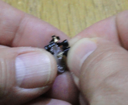
Next, release the microscopic catch-tabs that hold the headlight assembly in place by gently rocking the haousing in the slot until the housing pulls forward and is free of the smokebox door.
|
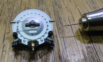
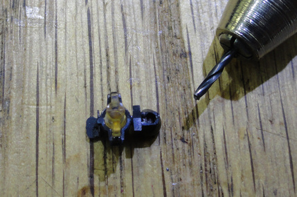
Then, drill a #80 hole through the smokebox door and bell/marker light bracket in the location where the MARS light housing is located.
|
Now we need to mount the LED to the headlight assembly.
Begin by drilling a #66 hole in the center of the back face of the upper lens housing. You can use the bit to push the lens out of the housing to clean out any drill shavings and flash from the hole.
|
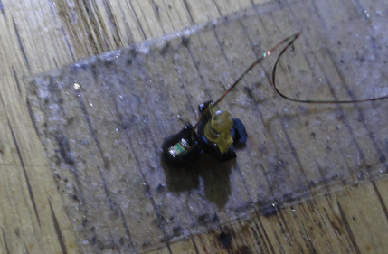
Add a weight if necessary to hold the LED in place until the glue has set up.
|
Once the glue is dried (I like to let it cure for about twenty-four hours), coat the backside of the assembly with black paint or Liquid Electrical Tape and repeat as necessary to "black out" any stray light.
As a side note, you can minimize the stray light in this step by using an SBS4DCC 0402 SMD Red Pre-Wired LED but they are really small and again, not for the faint of heart.
Then re-assemble the whole works, add six inch wire leads to the mag wire, and insulate the solder joints.
Be sure to re-attach the resistor to the negative (cathode) lead of the LED.
|
Now that the lighting is finished, there only a few additional steps to get the model ready for installation and re-assembly.
|
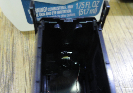
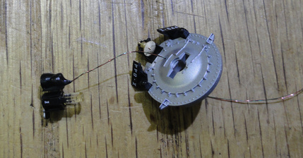
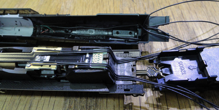
Next, I assemble the SBS4DCC 11x15mm "Sugar Cube" Speaker and secure it to the floor of the tender using a dollop of Liquid Electrical Tape.
I do not make any additional provisions for baffling or sound porting in this model. There is a large opening at the front of the tender assembly and the whole body acts as big bass tube when the speaker is mounted as shown. This arrangement seems to be quite sufficient for both volume and sound quality.
|
Installation and Final Assembly
|
With all of the final prep work complete and all of the glue dried, we can begin the final installation and re-assembly of the model.
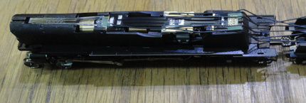
I like to reassemble the boiler and route the wiring to the tender first so that I can size the wire lengths more accurately.
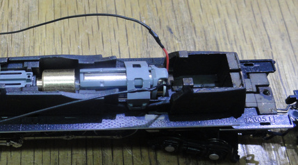
I begin by re-installing the circuit board. Installation is just the opposite of removal except that I push the insulated portion of the motor wires into the cavity behind the motor and route the wires out along the sides of the board.
|
Next, I bunch the wires together into two groups of three and hand form them to the contour of the chassis. Once they have taken shape and will conform easily, I lay boiler shell back on the chassis and secure in place with the retaining screw.
There is plenty of gap between the shell and frame for the wires so just be patient and work with the assembly until the wire bundles lay flat and organized.
You can use a bit of double sided tape to help keep everything organized until the shell is back on.
You could also add a small drop of Liquid Electrical Tape to hold them in place if they get really wild on you.
|
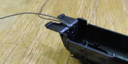
Be sure to check for any gap between the boiler shell and walkway tread plates. Adjust the wire bundles as needed so the shell fits neatly back together.
|
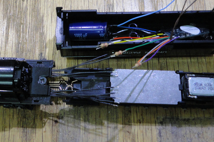
Next, I size the wire bundles and decoder harness for the splice joints to complete the install.
Since this is a hardwire installation, I have to remove the NEM652 8-pin plug from the decoder.
I lay the decoder assembly next to the tender in the approximate location of final assembly.
Using a pair of wire cutters, I cut the two wire bundles and the decoder harness so that the splice joint will lay between the front opening of the tender and the weight-keeper protrusion on the inside of the tender body. Be sure to leave a little extra for the wires to overlap.
|
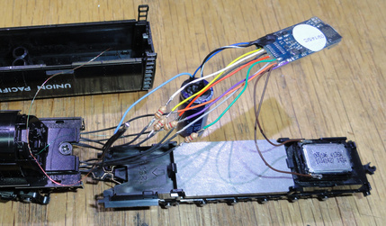
Then, strip and solder the wires together per the decoder manufactures directions.
In the case of the LokSound, color codes are as follows:
Red Right Rail Black Left Rail Orange Motor (+) Gray Motor (-) Blue Function Common White Front Headlight Yellow Rear Headlight Green AUX1 (Firebox Flicker) Violet AUX2 (Front MARS Headlight) Brown Speaker
Be sure to apply Liquid Electrical Tape to the exposed solder joints to prevent any short circuits between the decoder wires and other metal stuff.
|
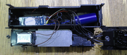
Once the Liquid Electrical Tape has dried, I lay the model on its side to fit the decoder in the tender shell.
Place a small "roll" of double sided tape on the roof inside the shell where the decoder and capacitor will sit and press the assembly onto the tape.
Once in place, organize the wires around the protrusion so that they won't get pinched when the floor and shell are mated back together.
|
And finally...
Press the tender shell and floor back together and set the unit right on its wheels.
Be sure to work the assembly in all directions of motion to be sure the wire bundles move freely. If a wire gets pinched, it may limit the motion of the drawbar connection and cause a derailment. Ask me how I know...
Then, snap the cab back in place.
Take a deep breath, get a drink, and relax. The hard part is finished.
|
So, with the hard part completed, we are off to the programming track.
Most vendors including myself, SBS4DCC.com, offer ESU LokSound decoders pre-programmed with any sound file you choose. In this case, I am using the Steam Locomotives Collection, file 73817.
Once the sound file is loaded, there a number of CV changes that need to be made to make the install perform as desired.
This process is most easily accomplished using an ESU LokProgrammer but it can be done with JMRI (version 3.8 or later) or even just your command station and a programming track.
For simplicity, I will break this out into three parts, general setup, motor tuning, and function programming.
Please note, these values work best for me and configure the model for my preferences.
You may have other preferences so refer to the manual for specific values for your needs and always make note of or a copy of initial values so that you can start over if you don't like your results.
|
General Setup:
These settings set the long address to the locomotive number, 844, and turn off a lot of features I do not use like Analog Conversion, Railcom, Brake On DC and such.
LokSound Select decoders offer configurable sound files so you can "Select" the sound that works best for your application.
These settings will also configure the sound selection for this file. In this example, I am going to use Prime Mover #1, Fast Bell type, and steam whistle #14, the 4-8-4 chuff with Union Pacific Hancock 3-chime steamboat style whistle.
Again, refer to the manual for your specific needs.
CV Settings:
CV13 = 0
CV14 = 0
CV17 = 195
CV18 = 76
CV27 = 0
CV28 = 0
CV29 = 34
CV47 = 1
CV50 = 0
CV13 = 0
CV14 = 0
CV17 = 195
CV18 = 76
CV27 = 0
CV28 = 0
CV29 = 34
CV47 = 1
CV50 = 0
CV13 = 0
CV14 = 0
CV17 = 195
CV18 = 76
CV27 = 0
CV28 = 0
CV29 = 34
CV47 = 1
CV50 = 0
CV13 = 0
CV14 = 0
CV17 = 195
CV18 = 76
CV27 = 0
CV28 = 0
CV29 = 34
CV47 = 1 CV48 = 78
CV50 = 0
|
Motor Tuning:
This is only the second install of thousands that did not like the factory settings of a LokSound and did not improve after running the LokSound Auto-Tune Procedure.
No doubt this is due to the use of the coreless motor. Most decoders require special effort to tune them for smooth performance when using this type of motor.
Note that CV52 and CV55 are adjusted to smooth out the motor control for the coreless motor.
Additional adjustments may be needed for your project.
Also note that CV57 and CV58 set the chuff timing on a LokSound. These settings worked perfectly to time the chuff at four beats per revolution. You may need to adjust these for your application.
CV Settings:
CV52 = 4
CV55 = 85
CV57 = 45
CV58 = 15
CV52 = 4
CV55 = 85
CV57 = 45
CV58 = 15
CV52 = 4
CV55 = 85
CV57 = 45
CV58 = 15
CV52 = 4
CV55 = 85
CV57 = 45
CV58 = 15
CV52 = 4
CV55 = 85
CV57 = 45
CV58 = 15
CV52 = 4
CV55 = 85
CV57 = 45
CV58 = 15
CV52 = 4
CV55 = 85
CV57 = 45
CV58 = 15
CV51 = 0 CV52 = 4 CV53 = 140 CV54 = 48
CV55 = 85 CV56 = 255
CV57 = 45
CV58 = 15
|
Function Control:
These setting configure the lighting in the stock file for use with this installation example only. Also note, these mapping choices are only available with the ESU line of decoders including the LokPilot and LokSound V4.0 and Select. No other brand on the market today offers 100% free function mapping the way Loks do. I had to remap a couple of ancillary sounds to make room in the lower range also.
I prefer to separate the front headlight from the rear headlight to different functions so that they are non-directional.
I set the Lower Headlight and Upper Headlight so that it can be On or MARS On, another lighting feature unique to the Loks. Note, this level of control is achieved through programming. All other decoder as of this writing would require two seperate function outputs to accomplish this.
I have also set the Upper Headlight so that when it on with F6, the MARS effect is activated when the whistle is blown, similar to the way ditch lights flash on a modern diesel when the horn is blown.
Again, refer to the manual for your specific needs.
The Revised Function Map will be as follows:
F0 Lower Headlight On / Dynamo (Dimmer)
F1 Bell
F2 Whistle
F3 Open Cylinder Cock
F4 Dimmer (Headlights)
F5 Rear Headlight (Dimmer)
F6 Upper Headlight On / Dynamo (Dimmer)
F7 Upper Headlight MARS On / Dynamo
F8 Volume Control / Mute
F9 Firebox Flicker
F10 Brake Set / Release
F11 Coal Shoveling
F12 Short Whistle
F13 Coupler
F14 Blower
F15 Injector
F16 Air Pump
F17 Oil Burner
F18 Sand Valve
F19 Crossing Communication
F20 Rail Clack
F21 Switching Mode
F22 Lower Headlight MARS On / Dynamo
F23 Dynamo Off
CV Settings:
CV31 = 16, CV32 = 0
----------------------
CV263 = 144
CV271 = 144
CV275 = 4
CV279 = 132
CV283 = 13
CV287 = 146
CV355 = 13
CV359 = 130
CV379 = 13
CV383 = 128
CV31 = 16, CV32 = 2
----------------------
CV282 = 1
CV315 = 0
CV331 = 0
CV334 = 0
CV336 = 2
CV348 = 64
CV350 = 0
CV362 = 2
CV366 = 32
CV378 = 8
CV382 = 32
CV395 = 128
CV396 = 0
CV398 = 32
CV426 = 4
CV428 = 32
CV446 = 0
CV447 = 8
CV463 = 64
CV479 = 128
CV490 = 0
CV494 = 16
CV510 = 128
CV511 = 0
CV31 = 16, CV32 = 3
----------------------
CV271 = 1
CV273 = 0
CV286 = 64
CV287 = 0
CV303 = 32
CV335 = 2
CV336 = 0
CV337 = 1
CV351 = 4
CV364 = 3
CV375 = 1
CV379 = 16
|
Additional Programming Updates
|
Two additional programming changes I have made to this model that diverge from the standard LokSound template are a unique configuration for volume control and Dynamo sound effect control.
You will note these change are reflected in the Revised Function Map as F8 (Volume Control / Mute) and F23 (Dynamo Off).
F8 Volume Control / Mute
The standard configuration for F8 is Sound On / Off.
Since this is a smoker with no real startup sequence, I just want the sound to be on with the ability to mute it when I need silence.
Also, because I do a lot shows and demonstrations, I want to be able to adjust the volume on the fly.
To accomplish this, I will assign the Volume Control Logical Function to F8 and standard engine sound slots to Forward and Reverse Conditions so they basically play all the time... unless muted with F8.
CV Settings:
CV31 = 16, CV32 = 2
----------------------
CV413 = 64
CV414 = 0
CV416 = 0
CV31 = 16, CV32 = 4
----------------------
CV257 = 4
CV270 = 3
CV272 = 129
CV273 = 8
CV286 = 3
CV288 = 129
CV31 = 16, CV32 = 2
----------------------
CV413 = 64
CV414 = 0
CV416 = 0
CV31 = 16, CV32 = 4
----------------------
CV257 = 4
CV270 = 3
CV272 = 129
CV273 = 8
CV286 = 3
CV288 = 129
F23 Dynamo Off
The Dynamo Sound Slot is assigned to F0 Function in all LokSound Select steam files.
While this may be prototypical, it may not always be desirable. Sometimes I just want the light on.
To accomplish this, I will un-assign the Dynamo Sound Slot from each of the lighting functions and create a new condition for each light function where the dynamo sound slot is assigned to a function that is on and the dynamo mute function is off.
Example: Conditions F0 (On), Not F23 (Off) ... Sound Slot 6 selected.
How this works...
When F0 is on and F23 is off, Sound Slot 6 plays.
When F0 is on and F23 is on, Sound Slot 6 does not play.
F23 is now a mute button for the Dynamo Sound Slot.
CV Settings:
CV31 = 16, CV32 = 2
----------------------
CV270 = 0
CV286 = 0
CV366 = 0
CV382 = 0
CV398 = 0
CV31 = 16, CV32 = 3
----------------------
CV385 = 16
CV391 = 8
CV398 = 32
CV402 = 64
CV407 = 8
CV414 = 32
CV419 = 1
CV423 = 8
CV430 = 32
CV435 = 4
CV439 = 8
CV446 = 32
CV455 = 9
CV462 = 32
CV31 = 16, CV32 = 2
----------------------
CV270 = 0
CV286 = 0
CV366 = 0
CV382 = 0
CV398 = 0
CV31 = 16, CV32 = 3
----------------------
CV385 = 16
CV391 = 8
CV398 = 32
CV402 = 64
CV407 = 8
CV414 = 32
CV419 = 1
CV423 = 8
CV430 = 32
CV435 = 4
CV439 = 8
CV446 = 32
CV455 = 9
CV462 = 32
CV31 = 16, CV32 = 2
----------------------
CV270 = 0
CV286 = 0
CV366 = 0
CV382 = 0
CV398 = 0
CV31 = 16, CV32 = 3
----------------------
CV385 = 16
CV391 = 8
CV398 = 32
CV402 = 64
CV407 = 8
CV414 = 32
CV419 = 1
CV423 = 8
CV430 = 32
CV435 = 4
CV439 = 8
CV446 = 32
CV455 = 9
CV462 = 32
|
Alternate F8 On / Off Control
|
CV31 = 16, CV32 = 2
----------------------
CV403 = 32
People frequently ask how to change F8 so that the sound is always on, and F8 turns it off. F8 on is the opposite of most other manufacturers and some folks want a Lok to operate that way.
To accomplish this, I will basically use the inverse condition of F8 or technically, Not F8.
So now, the assigned sound slots play until F8 is turned on.
CV Settings:
CV31 = 16, CV32 = 2
----------------------
CV403 = 32
NOTE: Do not use the values for F8 Volume Control if using Alternate F8 On / Off Control.
|
SBS4DCC Kato FEF-3 LokProgrammer File
|
For those with a LokProgrammer, here is a copy of the sound file with all of the settings already made.
|
The Test Run and Demonstration
|
So with that, the install is complete. Time to pour a glass and celebrate.
Or, if you are like me, curse, swear and try to sort out everything that wasn't quite as easy as it sounded here.
N' Joy!
|
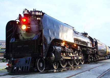
A sample of the 1:1 for reference...
|
A Neat Video of the MARS Light...
|
A Glamour Shot of #844... Illuminated...
|
Hancock Long-Bell 3-Chime Whistle Recordings
|
|
|